Multi-output antenna

a multi-output antenna and antenna technology, applied in the field of multi-output antennas, can solve the problems of not being able to support more than two services at the same time, not being able to access two, and not being able to fit all of these antennas, so as to increase the frequency tuning agility of the antenna, wide frequency tuning range, and wideband performance

Active Publication Date: 2014-06-12
SMART ANTENNA TECH
View PDF9 Cites 9 Cited by
  • Summary
  • Abstract
  • Description
  • Claims
  • Application Information

AI Technical Summary

Benefits of technology

[0037]In certain embodiments three or more radiating elements may be employed to further increase the frequency tuning agility of the antenna. A third or subsequent radiating element may be located within the first gap defined above. The third or subsequent radiating elements may be configured to operate at frequencies greater than 3 GHz.
[0038]It will be understood that a merit of employing an antenna as described

Problems solved by technology

It will therefore be challenging for mobile terminal designers to fit all of these antennas into the small amount of space which is available in a handset.
However, this antenna is only able to access two services simultaneously.
For example, the antenna can only support DVB-H (470 MHz) and GSM (900 MHz) signals or DVB-H (470 MHz) and WiFi (2400 MHz) or GSM (900 MHz) and GPS (1500 MHz) but it cannot support more than two of these services simultaneously, as requir

Method used


Image

  • Multi-output antenna
  • Multi-output antenna
  • Multi-output antenna

Examples


Embodiment Construction

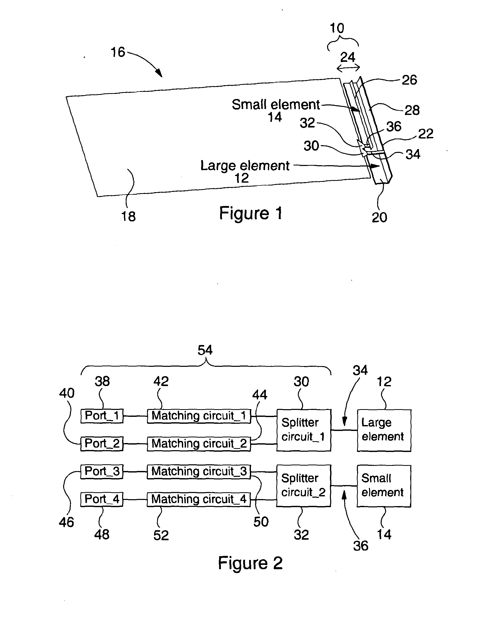
[0092]With reference to FIG. 1 there is shown a pair 10 of coupled radiating elements 12, 14 for an antenna 16 according to an embodiment of the present invention. The radiating elements 12, 14 are similar to those described in WO2011 / 048357, are mounted in close proximity to each other and are driven over a PCB ground plane 18. Although, in practice, the radiating elements 12, 14 and ground plane 18 are provided on a substrate, no substrate is shown in FIG. 1 for purposes of clarity.

[0093]It should be noted that the antenna 16 is fairly simple in construction and in having the ground plane 18 measuring 100×40 mm2 and the pair 10 of radiating elements 12, 14 occupying a very small volumetric space of 40×5×7 mm3, the antenna 16 meets the requirements for use in the mobile phone industry.

[0094]In this particular embodiment, the first radiating element 12 is constituted by an L-shaped microstrip patch having a planar portion 20, parallel to the ground plane 18, and an orthogonal portio...


PUM


Abstract

A reconfigurable multi-output antenna (16) is disclosed comprising: one or more radiating elements (12, 14), at least two matching circuits (42, 44, 50, 52) coupled to the or each radiating element (12, 14) via e.g. a splitter (30, 32) or a diplxer; and wherein each matching circuit (42, 44, 50, 52) is associated with a separate port (38, 40, 46, 48) arranged to drive a separate resonant frequency so that the or each radiating element (12, 14) is operable to provide multiple outputs simultaneously. The resonant frequency of each output is independently controllable by each matching circuit, with good isolation with each other port, thereby offering very wide operating frequency range with simultaneous multi-independent output operations. Also described is a multi-output antenna control module for coupling to one or more radiating elements, an antenna structure and an antenna interface module. A reconfigurable multi-output antenna is disclosed comprising: one or more radiating

Description

FIELD OF THE INVENTION[0001]The invention relates to a multi-output antenna. Particularly, but not exclusively, the invention relates to a multi-output antenna for use in a portable electronic device such as a mobile telephone, laptop, personal digital assistant (PDA) or radio.BACKGROUND TO THE INVENTION[0002]With growing requirements for connectivity in a highly mobile environment, more standards and services are being rolled out (such as DVB-H, RFID, RDF, UWB, LTE etc). For this reason some believe that future mobile terminals will need to incorporate more than 20 separate antennas. It will therefore be challenging for mobile terminal designers to fit all of these antennas into the small amount of space which is available in a handset.[0003]There are many proposals for reconfigurable antenna designs which would help to alleviate this problem. In particular, the applicants have devised a reconfigurable antenna described in WO2011 / 048357 which has an extremely wide tuning range. How...

Claims


Application Information

Patent Timeline
IPC IPC(8): H01Q21/00H01Q5/10H01Q5/335
CPCH01Q1/243H01Q21/28H01Q5/335H01Q21/0006
Inventor HALL, PETERHU, ZHENHUA
Owner SMART ANTENNA TECH
Why Eureka
Try Eureka