Modular LED lamp structure with replaceable modules

a module and led lamp technology, applied in the field of led lamps, can solve the problems of shortened life, high light fade, comparatively high heat energy, etc., and achieve the effect of rapid repair and maintenance, simplified structure and easy mass production

Inactive Publication Date: 2014-06-12
WU MING YUAN
View PDF1 Cites 48 Cited by
  • Summary
  • Abstract
  • Description
  • Claims
  • Application Information

AI Technical Summary

Benefits of technology

[0007]The present invention overcomes the above-described and other problems and disadvantages in the prior art by providing a LED lamp with simplified structure to mass-produce easily with cost down and to enable rapid repair and maintenance.

Problems solved by technology

However, LEDs would generate comparatively high heat energy, with a result of their high light fades and shortened life span.
This leads to limited applications of LEDs to some extent.
The LED array structure may satisfy the requirement for illuminance, but it causes several problems including heat concentration, and high temperature at local positions.
Because of the absence of specialized means for heat conduction and heat dissipation, the heat energy generated by the plurality of LED light sources cannot be effectively dissipated, such that the temperature of the housing of the lamp is so high to the extent that people would get scalded and that this lamp is vulnerable to get burned out.
This causes the structure of the LED lamp to be more complex.
Therefore, the conventional LED lighting device lacks the flexibility of assembling and is not economical.
Furthermore, when parts of the LED lamp is in failure and needs replacement, it can not replace the failure part only and has to replace the entire LED lamp.
In other words, the other non-failure parts are also replaced as well as the failure parts at the same time, which is in causing unnecessary waste.

Method used


Image

  • Modular LED lamp structure with replaceable modules
  • Modular LED lamp structure with replaceable modules
  • Modular LED lamp structure with replaceable modules

Examples


Embodiment Construction

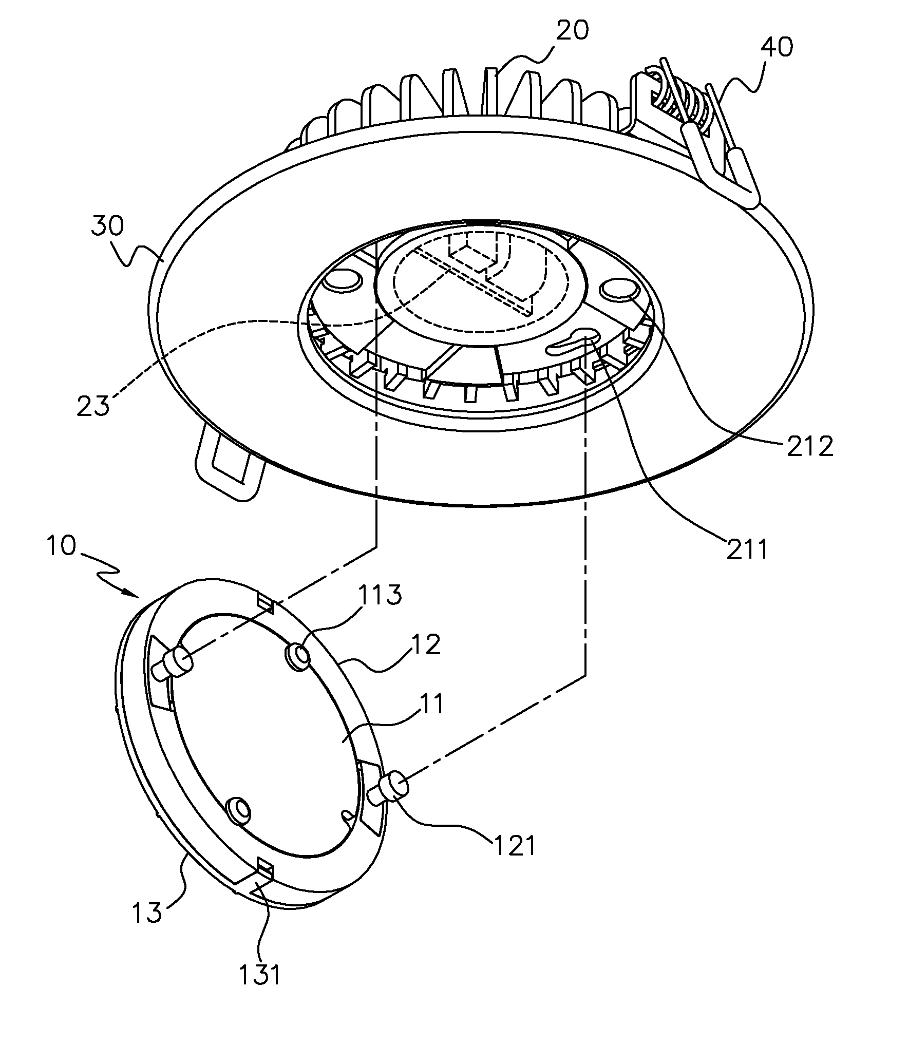
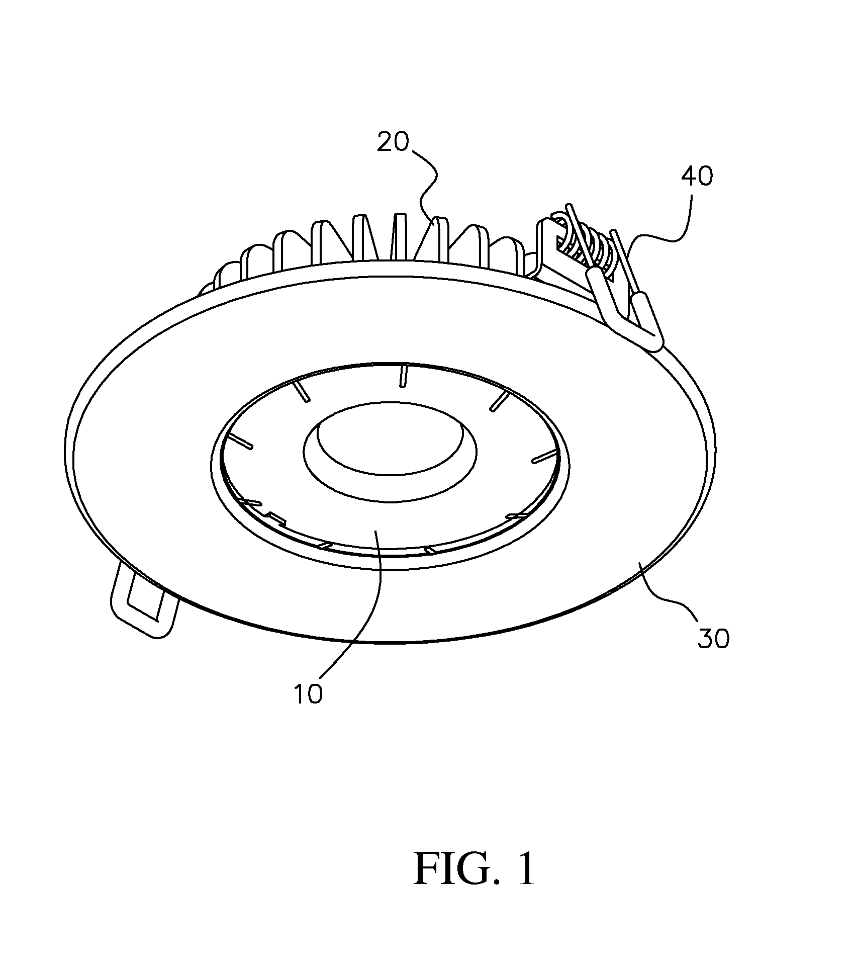
[0017]A LED lamp structure used for the purpose of illumination according to the present invention is shown in FIG. 1. The LED lamp structure includes a light emitting module 10, a radiator module 20, a supporting ring 30, and an elastic fastener 40. As shown in FIG. 1, the LED lamp is a recessed light. The supporting ring 30 has the to fix the elastic fastener 40, see FIG. 2B. The supporting ring 30 and the elastic fastener 40 are configured to be embedded in a floor, wall or ceiling.

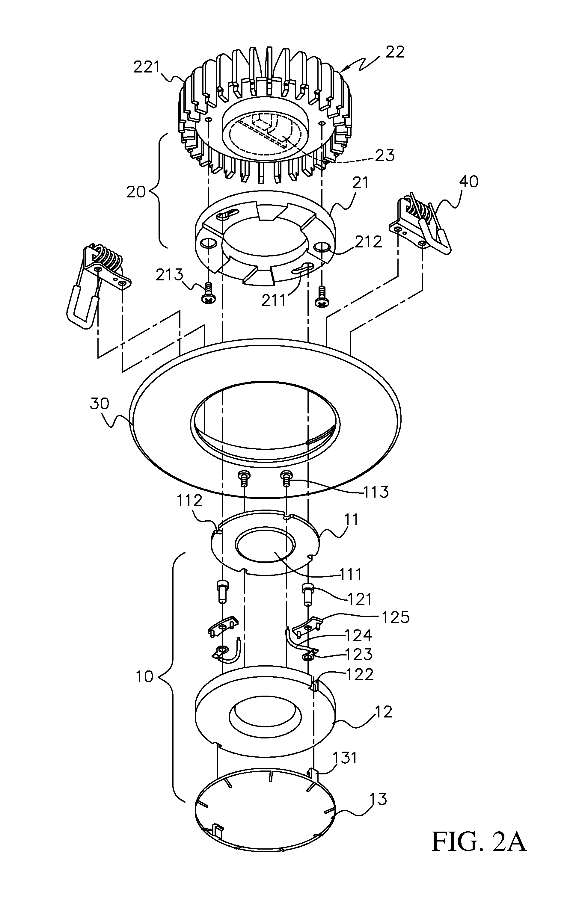
[0018]Please refer to FIGS. 2A-2B, the light emitting module 10 includes a substrate 11, a body 12 and a lamp cover 13. The substrate 11 is supported by the body 12. A plurality of LEDs 111 are disposed on the substrate 11 and configured to emit lights. The LEDs 111 may be a surface mounting device (SMD) or have a chip on board (COB) package structure. The lamp cover 13 is disposed on the body 12 and covers the substrate 11 to protect the LEDs 111. The lamp cover 13 can be made of glass, a polymer, or ...


PUM


Abstract

A LED lamp structure includes a LED emitting module and a radiator module. The radiator module includes a holder with an elastic slice to connect electrically to a driver unit for supplying power. The driver unit may be disposed in the radiator module or within the LED emitting module. Therefore, the structure of the LED lamp is simplified. The modules can be replaced when they break down, without having to discard the whole set of LED lamp, thus eliminating the unnecessary waste, in achieving cost-effectiveness and environment protection.

Description

BACKGROUND OF THE INVENTION[0001]1. Field of Invention[0002]The present invention relates to a LED lamp, in particular to a LED lamp structure used for the purpose of illumination with replaceable modules.[0003]2. Related Art[0004]As a solid state light source, LEDs (light-emitting diodes) are a product with long life span, firm structure, low power consumption and flexible dimension such that they are becoming to take the place of conventional high pressure halide lamps in a wide range of lighting applications. However, LEDs would generate comparatively high heat energy, with a result of their high light fades and shortened life span. This leads to limited applications of LEDs to some extent.[0005]A currently available LED lamp, which is used for the purpose of illumination, usually comprises a plurality of LED light sources to form a LED array in order to reach the required illuminance and power, because a single one LED light source has relatively low illuminance and power. The L...

Claims


Application Information

Patent Timeline
Patent Type & Authority Applications(United States)
IPC IPC(8): F21V21/00F21V29/00
CPCF21S8/026F21V17/14F21V21/04F21K9/20F21Y2115/10F21V17/002F21S8/02Y02B20/30F21V29/77
Inventor WU, MING-YUAN
Owner WU MING YUAN
Why Eureka
Try Eureka