Optically driven active radiator

a radiator and optical drive technology, applied in the field of radiators, can solve the problems of increasing ineffective high frequency power transfer techniques such as solder balls or solder bumps to off-chip loads (e.g., external antennas)

Active Publication Date: 2014-06-12
CALIFORNIA INST OF TECH
View PDF8 Cites 17 Cited by
  • Summary
  • Abstract
  • Description
  • Claims
  • Application Information

AI Technical Summary

Problems solved by technology

However, to use the CMOS technology at such high frequencies, many technical challenges need to be overcome.
Radiation, on-chip power generation, impedance matching, and transfer of power off-chip also pose challenges.
For example, traditional power transfer techniques, such as bonding wires, solder balls or solder bumps to off-chip loads (e.g., external antennas) also become increasingly ineffective at high frequencies.

Method used


Image

  • Optically driven active radiator
  • Optically driven active radiator
  • Optically driven active radiator

Examples


Embodiment Construction

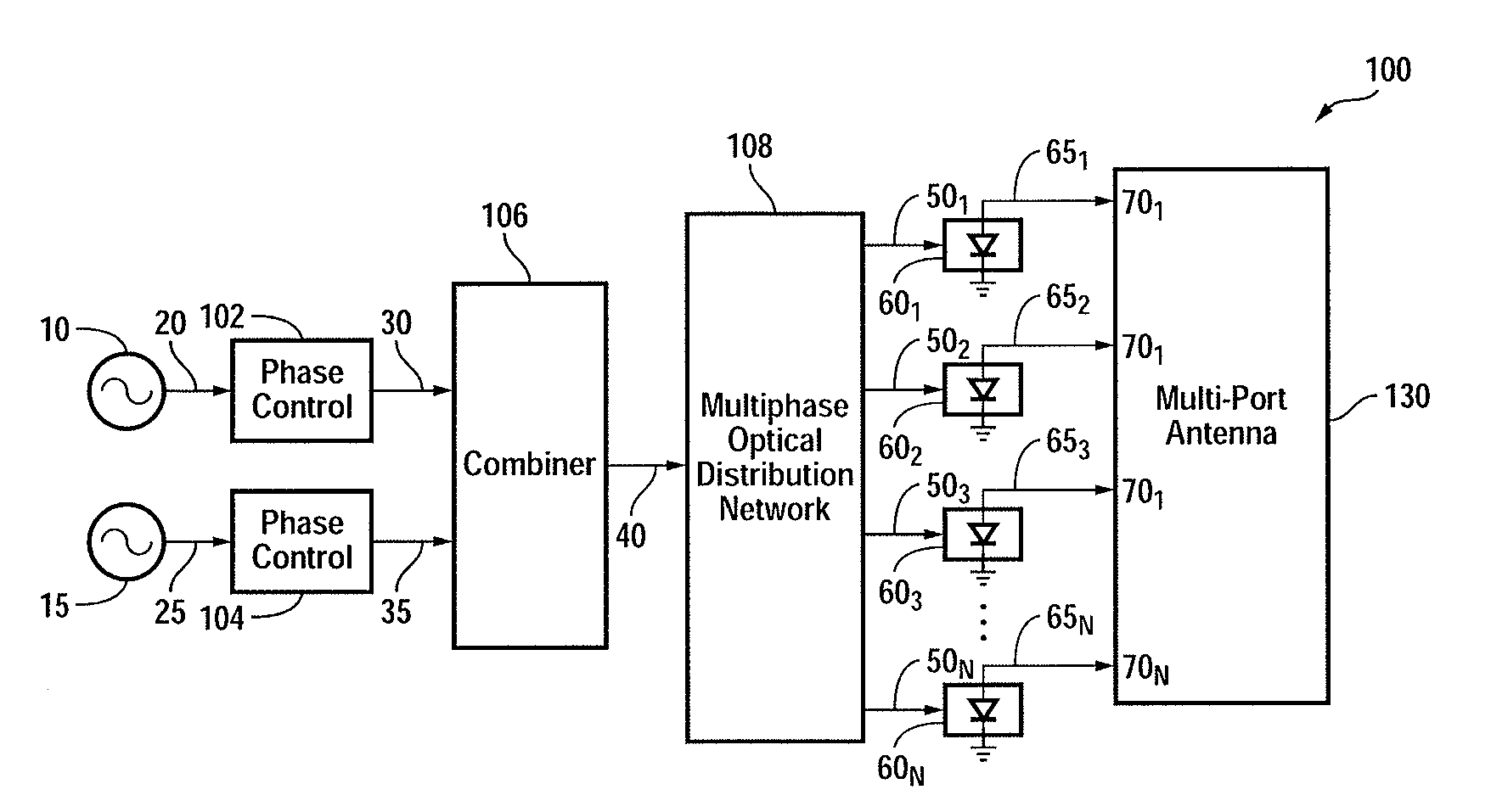
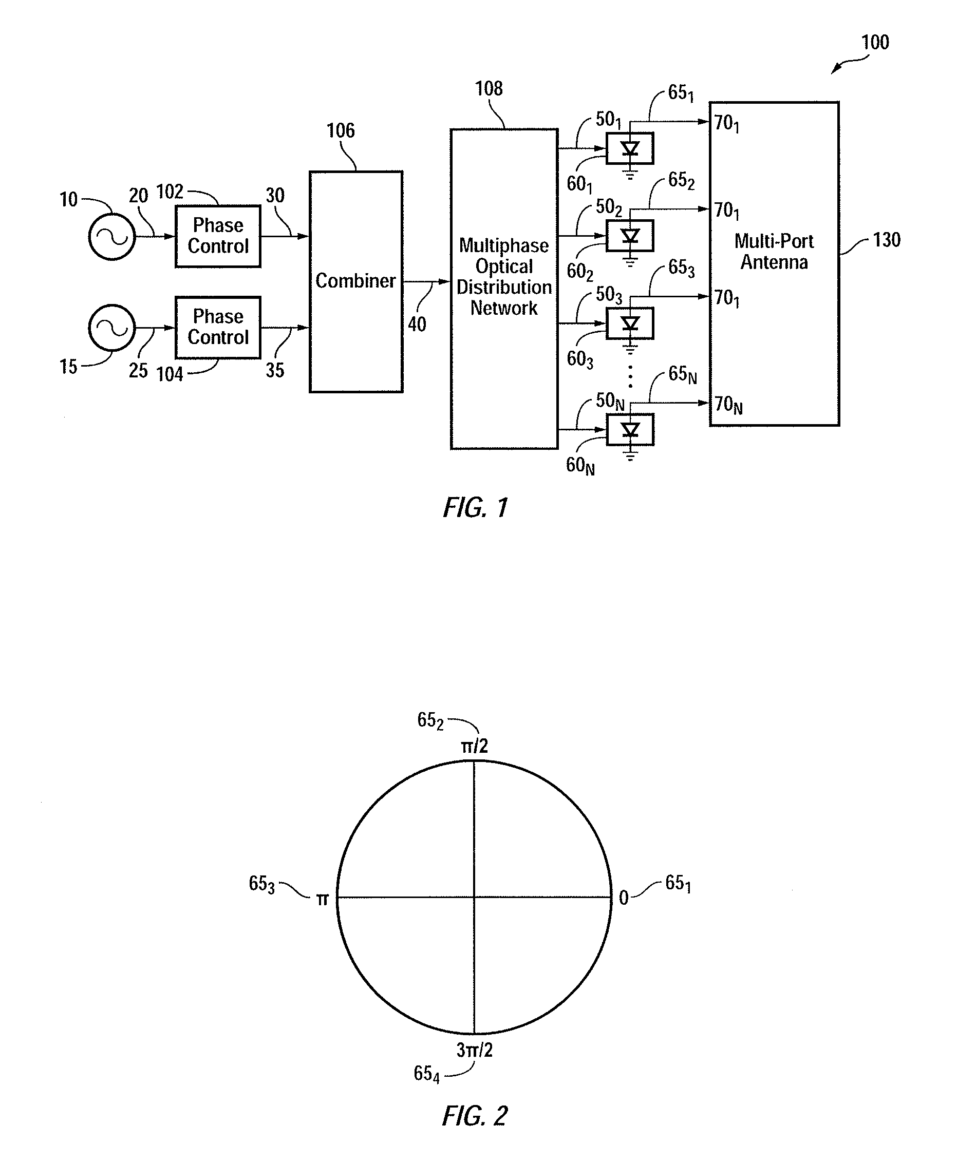
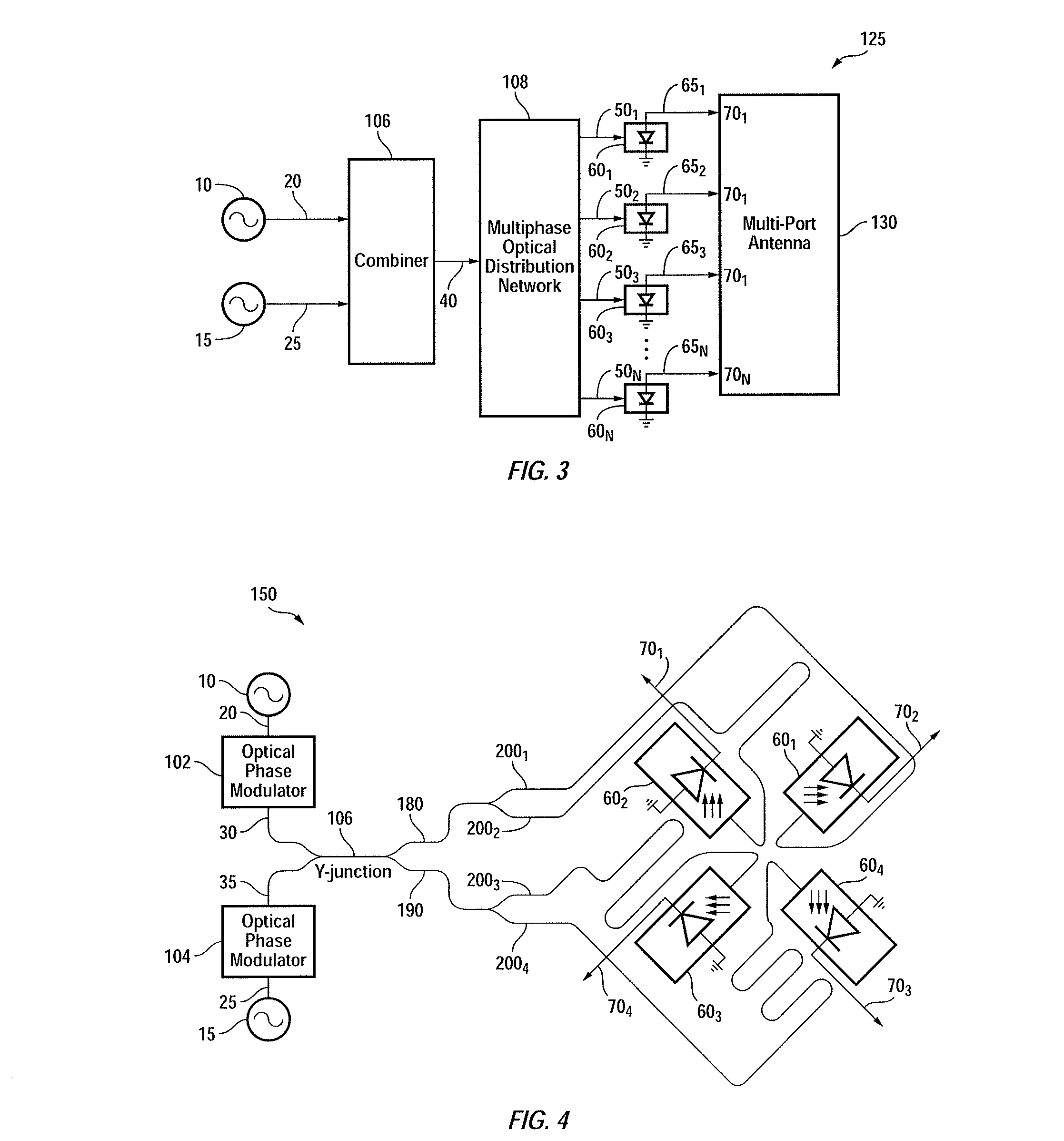
[0029]FIG. 1 is a block diagram of a multi-port radiator 100, in accordance with one exemplary embodiment of the present invention. Multi-port radiator (alternatively referred to herein as radiator) 100 is shown as including phase control blocks 102, 104, signal combiner 106, multi-phase optical distribution network 108, frequency conversion elements 60i, where an index varying from 1 to N and N is an integer greater than 1, and antenna 130 having N input ports. Phase modulator / control block 102 is adapted to control / modulate the phase of optical signal 20 received from optical source 10, thereby to generate phase-modulated signal 30. Likewise, phase modulator / control block 104 is adapted to control / modulate the phase of optical signal 25 received from optical source 15, thereby to generate phase-modulated signal 35. Optical sources 10 and 20 may be lasers generating relatively high frequency signals (e.g., THZ

[0030]Combiner 106 is adapted to combine signals 30 and 35 so as to form ...


PUM


Abstract

A multi-port radiator radiates electromagnetic signal in response to a beat frequency of a pair of optical signals. The radiator includes a multitude of optical paths each carrying an optical signal having first and second wavelengths. A multitude of frequency conversion elements convert the optical signals to electrical signals and deliver them to the radiator's multiple ports. The frequency of the electrical signals, and hence the frequency of the electromagnetic wave, is defined by the difference between the first and second wavelengths. The phases of the optical signals received by the frequency conversion elements are shifted with respect to one another. Optionally, the difference between the phases of the optical signals travelling through each pair of adjacent paths is 90°. The first and second wavelengths are generated by a pair of optical sources and are optionally modulated before being combined and delivered to the optical paths.

Description

CROSS-REFERENCES TO RELATED APPLICATIONS[0001]The present application claims the benefit of U.S. provisional application No. 61 / 676,154, filed Jul. 26, 2012, entitled “OPTICALLY DRIVEN ACTIVE RADIATOR”, the contents of which is incorporated herein by reference in its entirety. The present application is also related to U.S. application Ser. No. 13 / 654,420, filed Oct. 18, 2012, entitled “EFFICIENT ACTIVE MULTI-DRIVE RADIATOR”, and U.S. application ser. No. 13 / 770,935, filed Feb. 19, 2013, entitled “DYNAMIC POLARIZATION MODULATION AND CONTROL”, the contents of which are also incorporated herein by reference in their entirety.STATEMENT AS TO RIGHTS TO INVENTIONS MADE UNDER FEDERALLY SPONSORED RESEARCH AND DEVELOPMENT[0002]The present invention was made with government support under FA8650-09-C-7924 awarded by USAF / ESC. The government has certain rights in the invention.FIELD OF THE INVENTION[0003]The present invention relates generally to a radiator radiating electro-magentic waves, an...

Claims


Application Information

Patent Timeline
Patent Type & Authority Applications(United States)
IPC IPC(8): H04B10/2575
CPCH04B10/2575H04B10/90H04B2210/006
Inventor BOWERS, STEVENAFLATOUNI, FIROOZABIRI, BEHROOZHAJIMIRI, SEYED ALI
Owner CALIFORNIA INST OF TECH
Why Eureka
Try Eureka