Scanning Systems for Particle Cancer Therapy

a particle cancer and scanning system technology, applied in the field of medical particle delivery system and transfer scanning system, can solve the problems of large magnet size, large equipment cost, and high cost of proton and especially carbon ions in the delivery system of proton and especially carbon ions, and achieve the effect of small magnet size and small dispersion function

Active Publication Date: 2014-06-12
BROOKHAVEN SCI ASSOCS
View PDF1 Cites 19 Cited by
  • Summary
  • Abstract
  • Description
  • Claims
  • Application Information

AI Technical Summary

Benefits of technology

[0017]A transfer system of a plurality of small magnets is arranged sequentially along the beam tube to transfer the particle beam from the particle beam entry point with strong focusing and with a small dispersion function, such that a beam size in the transfer system is very small, thereby allowing for the small size of the magnets.
[0019]A scanning system of magnets arranged along the beam tube after the bending system and before the particle beam exit point delivers the particle beam from the particle beam exit point to the patient in a direction normal to the patient, thereby minimizing exposure to the ion beam of healthy skin and tissue. The scanning system of magnets includes a first scanning magnet and a second scanning magnet. The first scanning magnet is a small aperture magnet, and the second scanning magnet is a large-aperture magnet. The second scanning magnet delivers the particle beam in a direction normal to the patient. Advantageously, the present invention obviates the need for the very large magnets at the end of the gantry, in contrast to other operating existing gantries.

Problems solved by technology

The gantry delivery systems for proton and especially carbon ions typically are the most expensive part of any treatment facility.
Because of these requirements, the gantry of a conventional particle beam cancer therapy facility is typically the most expensive piece of equipment of the treatment facility and its magnets are generally very large and heavy.
This extreme weight results in significant amount of structural cost for a building that can support this massive rotating gantry weight.

Method used


Image

  • Scanning Systems for Particle Cancer Therapy
  • Scanning Systems for Particle Cancer Therapy
  • Scanning Systems for Particle Cancer Therapy

Examples


Embodiment Construction

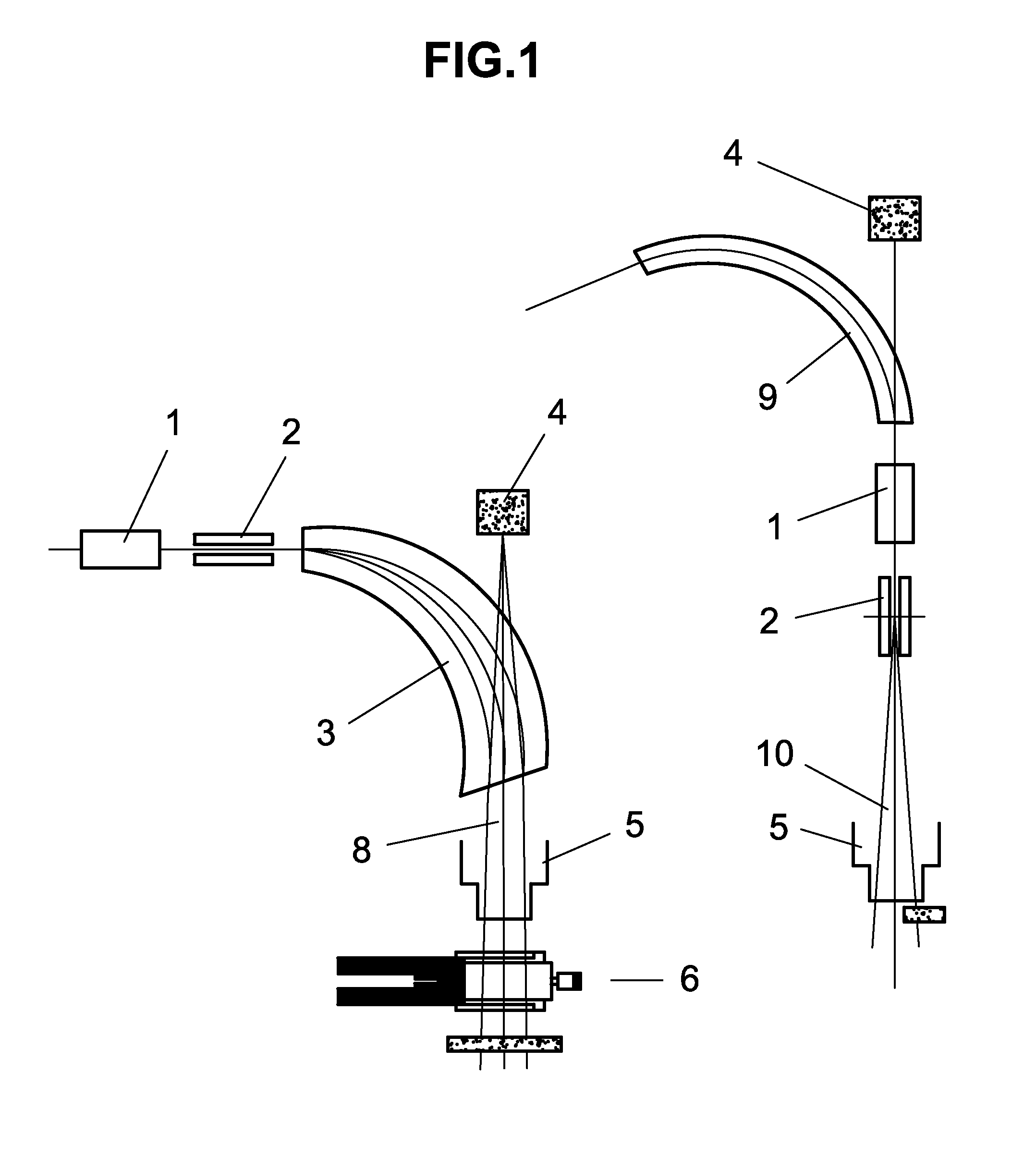
[0032]Referring initially to FIG. 1, illustrated are two prior art scanning solutions, with gantries shown in side view. The first part of the picture at the left lower side shows one plane scanning magnet 1, a scanning magnet 2, a large bending magnet 3, an X-ray tube 4, a schematic presentation of the nozzle 5, a patient 6, below the nozzle 5, and the shielding below the patient 6. The emphasis is on parallel beam 8 directed towards the patient 6. On the right hand side of FIG. 1, a plane scanning magnet 1 and a scanning magnet 2 are positioned downstream of a smaller bending magnet 9. A particle beam 10 may be directed toward a patient via the nozzle 5. The beam arrives to the patient with angles defined by the distance between the scanning magnet and the patient 10 and a loss of parallel beam condition.

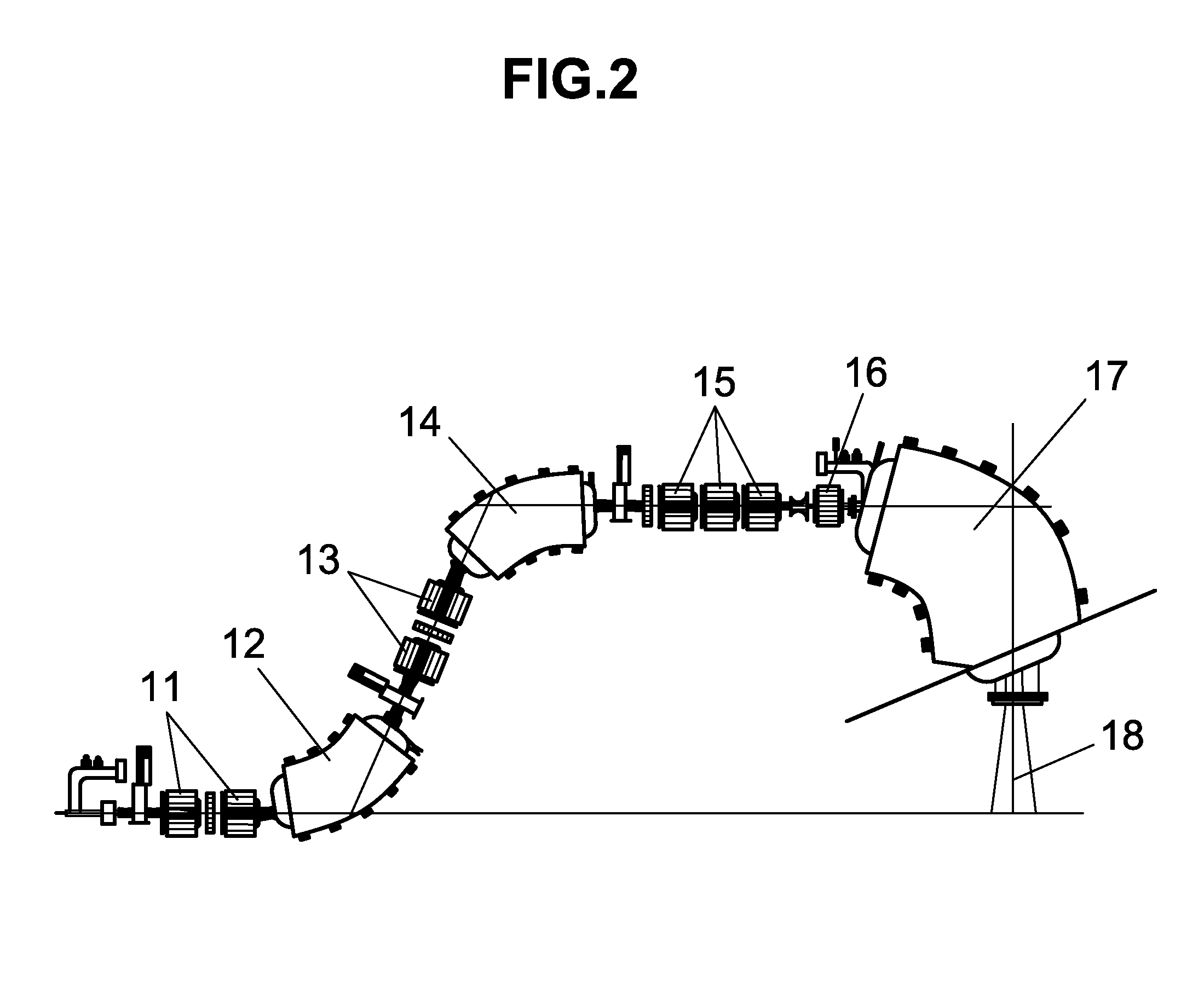
[0033]FIG. 2 illustrates a prior art gantry system at the PSI. The PSI gantry system contains first doublet quadrupoles 11, first bending dipole 12, second doublet quadrupoles 13,...


PUM


Abstract

A particle beam to treat malignant tissue is delivered to a patient by a gantry. The gantry includes a plurality of small magnets sequentially arranged along a beam tube to transfer the particle beam with strong focusing and a small dispersion function, whereby a beam size is very small, allowing for the small magnet size. Magnets arranged along the beam tube uses combined function magnets where the magnetic field is a combination of a bending dipole field with a focusing or defocusing quadrupole field. A triplet set of combined function magnets defines the beam size at the patient. A scanning system of magnets arranged along the beam tube after the bending system delivers the particle beam in a direction normal to the patient, to minimize healthy skin and tissue exposure to the particle beam.

Description

CROSS-REFERENCE TO RELATED APPLICATIONS[0001]This application claims the benefit of U.S. Provisional Application No. 61 / 734,493 filed Dec. 7, 2012.STATEMENT OF GOVERNMENT LICENSE RIGHTS[0002]This invention was made with Government support under contract number DE-AC02-98CH10886, awarded by the U.S. Department of Energy. The Government has certain rights in the invention.BACKGROUND[0003]The present invention relates generally to a medical cancer therapy facility and, more particularly, to a medical particle delivery system having a compact gantry design. Embodiments of the invention relate to apparatuses and methods for transfer scanning systems for use in cancer therapy.[0004]Subject matter of the invention pertains to methods and apparatus for using, generating, controlling or detecting radiant energy, that is, energy propagated in the form of electromagnetic waves, or traveling subatomic, atomic or molecular particles, combinations and subcombinations including such methods or app...

Claims


Application Information

Patent Timeline
Patent Type & Authority Applications(United States)
IPC IPC(8): A61N5/10
CPCA61N5/1077A61N5/1043A61N5/1081A61N2005/1087
Inventor TRBOJEVIC, DEJAN
Owner BROOKHAVEN SCI ASSOCS
Why Eureka
Try Eureka