Eureka AIR delivers breakthrough ideas for toughest innovation challenges, trusted by R&D personnel around the world.

Heat dissipation composite

Inactive Publication Date: 2014-06-19
DIODE ON OPTOELECTRONICS
View PDF7 Cites 0 Cited by
  • Summary
  • Abstract
  • Description
  • Claims
  • Application Information

AI Technical Summary

Benefits of technology

The invention provides a heat dissipation composite without using polymer adhesive. It has a metal substrate, a metal bonding layer, and a ceramic layer. The metal bonding layer has a lower melting point than the metal substrate and is formed on the metal substrate through metal-to-metal bonding. The ceramic layer is composed of ceramic powders and is covered on and bonded to the metal bonding layer opposite to the metal substrate. This composite has improved heat dissipation properties and can be used in electronic devices.

Problems solved by technology

Many electronic devices generate great amounts of heat when being used.
The elevated temperature caused by heat generation compromises efficiency of the electronic devices.
Taking an LED light bulb as an example, high temperature caused by heat generation during illumination compromises LED luminous efficacy and might even damage the LED light bulb.
Most adhesives, however, are made of polymer which has low thermal conductivity and which impairs thermal dissipation of the ceramic layer.

Method used


Image

  • Heat dissipation composite
  • Heat dissipation composite
  • Heat dissipation composite

Examples


Embodiment Construction

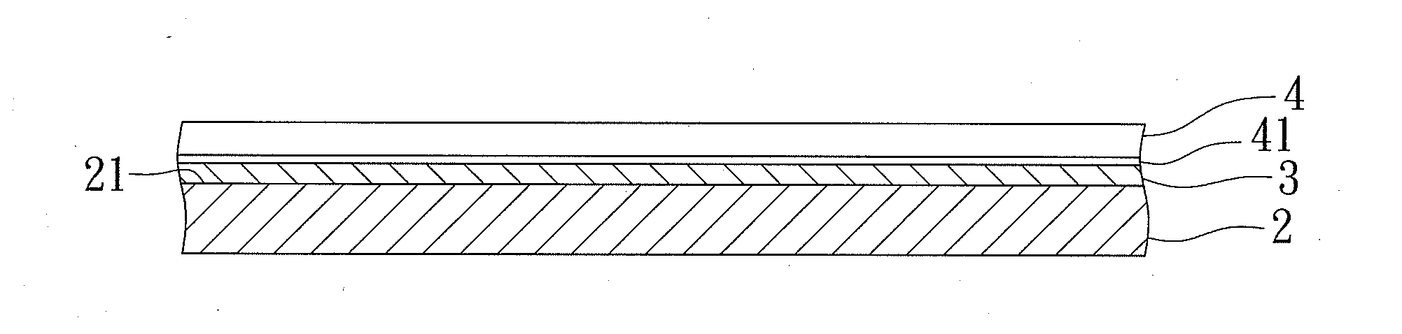
[0016]Referring to FIG. 1, the preferred embodiment of a heat dissipation composite according to this invention has a metal substrate 2, a metal bonding layer 3, and a ceramic layer 4.

[0017]The metal substrate 2 can be made of any suitable metal material according to its application field. In the preferred embodiment of this invention, the metal substrate 2 is used in LED light bulbs and therefore is preferably made of copper having a melting point of 1084° C.

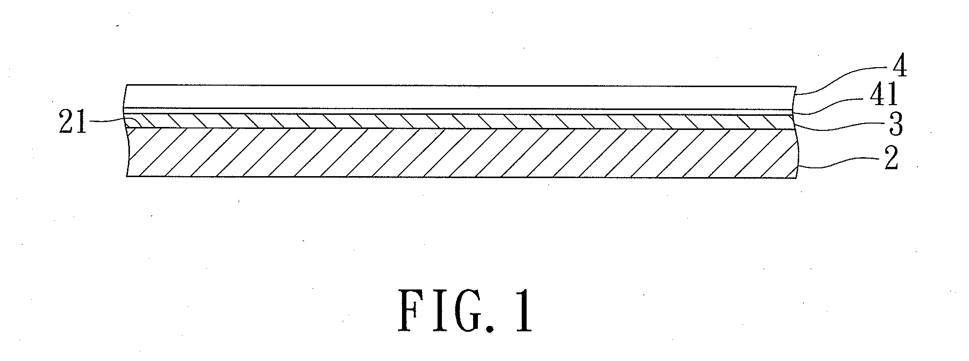
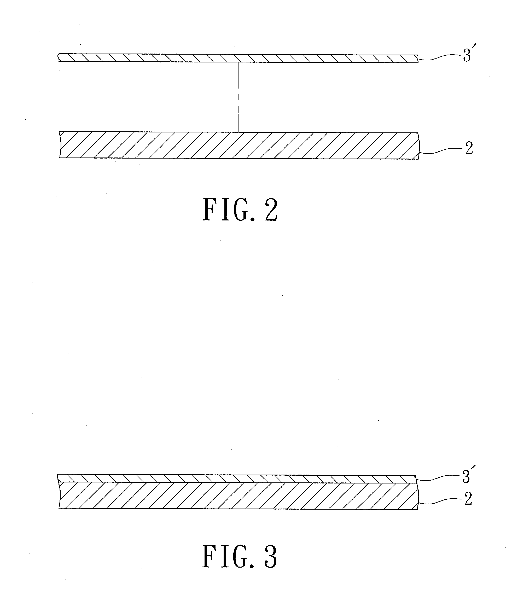
[0018]The metal bonding layer 3 has a melting point lower than that of the metal substrate 2 and is formed on a surface 21 of the metal substrate 2 through metal-to-metal bonding. The metal bonding layer 3 preferably has low thermal resistance. In the preferred embodiment of this invention, the metal bonding layer 3 is made of tin which has a melting point of 232° C. The metal bonding layer 3 can be made of other metals as long as the melting point of the metal bonding layer 3 is lower than the melting point of the metal substr...


PUM


Abstract

Disclosed herein is a heat dissipation composite having a metal substrate, a metal bonding layer, and a ceramic layer. The metal bonding layer has a melting point lower than that of the metal substrate and is formed on the metal substrate through metal-to-metal bonding. The ceramic layer is composed of ceramic powders and is covered on and bonded to the metal bonding layer opposite to the metal substrate.

Description

BACKGROUND OF THE INVENTION[0001]1. Field of the Invention[0002]This invention relates to a heat dissipation composite, more particularly to a heat dissipation composite without polymer adhesive.[0003]2. Description of the Related Art[0004]Many electronic devices generate great amounts of heat when being used. The elevated temperature caused by heat generation compromises efficiency of the electronic devices. Taking an LED light bulb as an example, high temperature caused by heat generation during illumination compromises LED luminous efficacy and might even damage the LED light bulb. Therefore, heat dissipation materials are likely to be used in an LED light bulb so as to reduce temperature in the bulb.[0005]A metal layer coated with a ceramic layer is used as a heat dissipating composite for a conventional LED light bulb. The ceramic layer is capable of absorbing and radiating heat generated by the LED light bulb. The temperature in the LED light bulb is decreased and the lighting...

Claims


Application Information

Patent Timeline
IPC IPC(8): F21V29/00F28F21/08F28F21/04
CPCF21V29/004F28F21/081F28F21/04F21V29/85F28D2021/0029F28F13/18F21K9/23F21Y2115/10
Inventor LIU, IVANLIU, SHU-PING
Owner DIODE ON OPTOELECTRONICS
Why Eureka
Eureka Blog
Learn More