Clamping and ligation device

a ligation device and ligature technology, applied in the field of medical devices, can solve the problems of increased difficulty of operation, large inserting force of ligation device, and insufficient containment of clamp in the locking device, and achieve the effects of small inserting force, easy discharge, and simple structur

a ligation device and ligature technology, applied in the field of medical devices, can solve the problems of increased difficulty of operation, large inserting force of ligation device, and insufficient containment of clamp in the locking device, and achieve the effects of small inserting force, easy discharge, and simple structur

US20140171974A1Active Publication Date: 2014-06-19HANGZHOU AGS MEDTECH CO LTD

Image

  • Clamping and ligation device
  • Clamping and ligation device
  • Clamping and ligation device

Examples


Embodiment Construction

[0073]The embodiments of the present invention are disclosed in detail by combining with figures below.

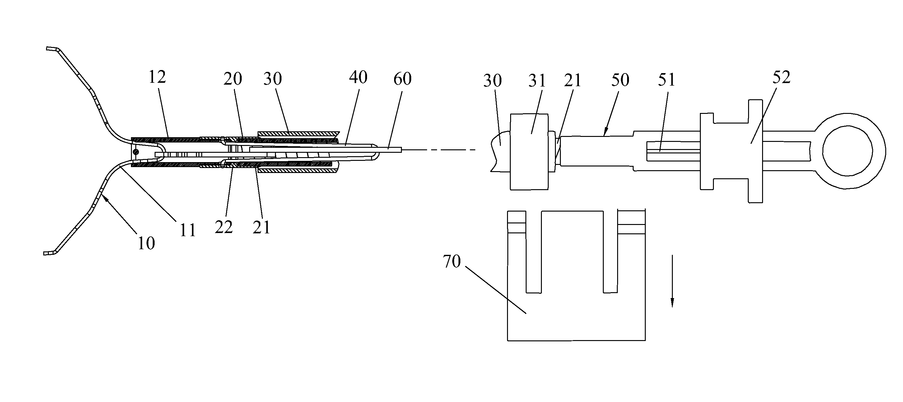
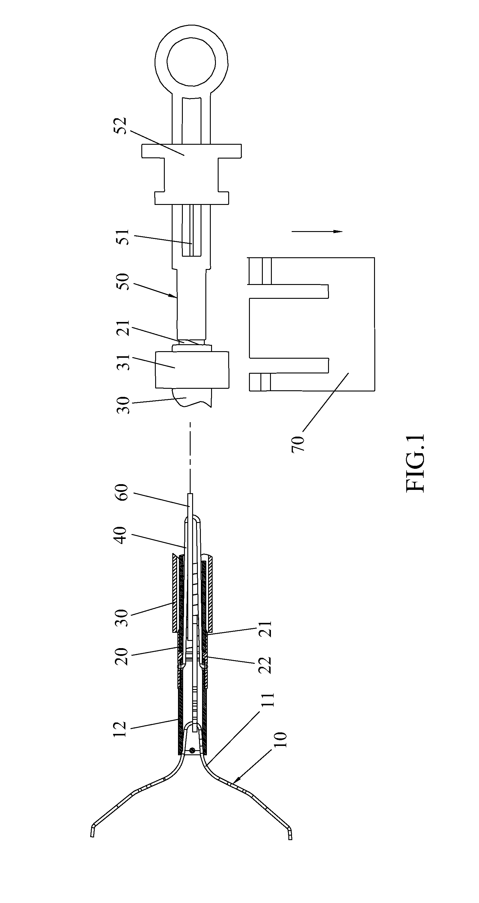
[0074]FIG. 1 demonstrates a whole structure of the clamping and ligation device according to an embodiment of the present invention. Referring to FIGS. 1-3, the clamping and ligation device includes a ligation unit 10, a conveying unit 20, a protective sleeve 30, a connecting unit 40, an operation unit 50, and a traction unit 60. Below is a detailed description.
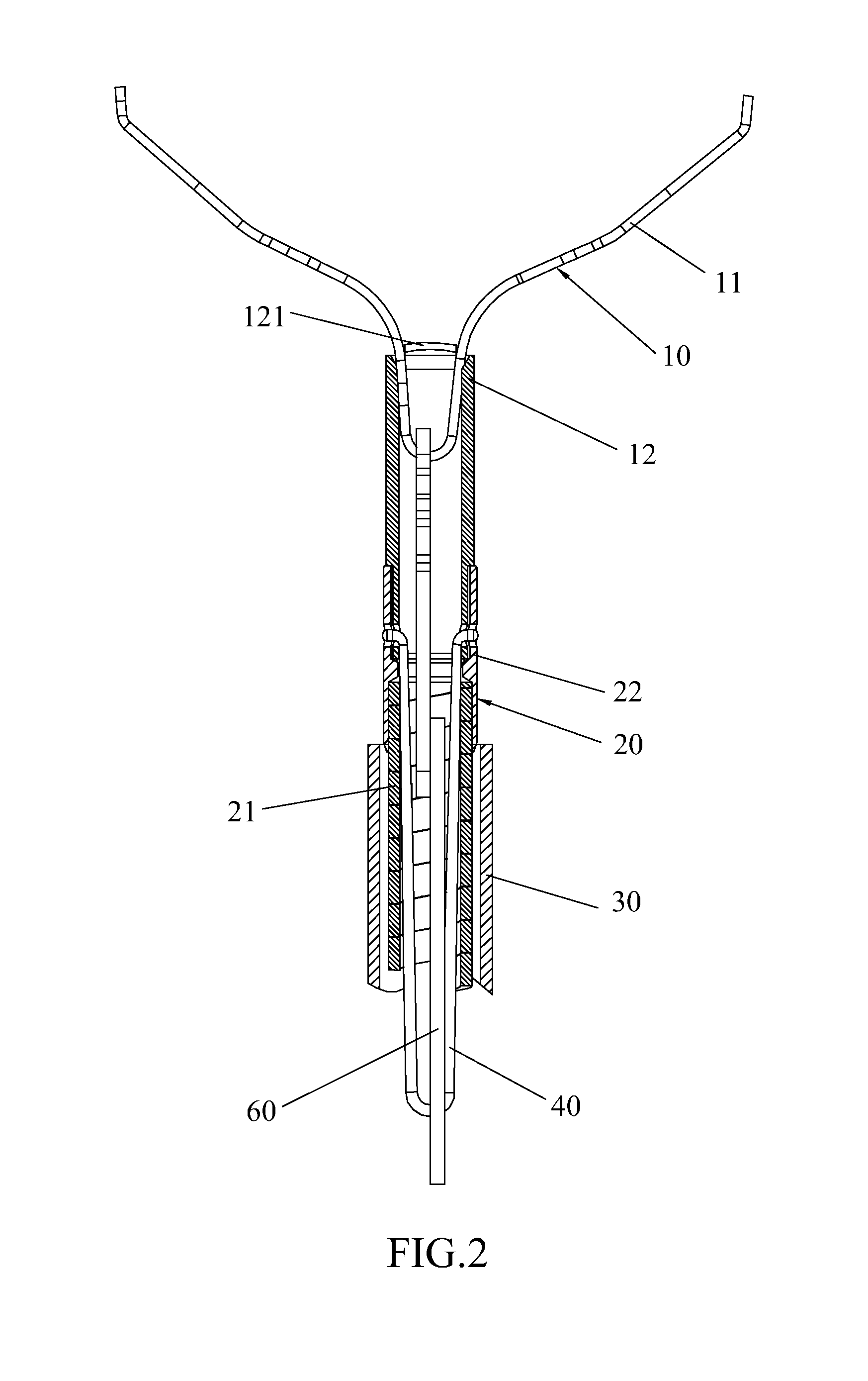
Ligation Unit

[0075]A ligation unit 10 includes a ligation component 11 and an accommodation tube 12 in which the ligation component 11 is housed; the ligation unit 10 could be remained in a digestive tract of a living body for some time and then falls off automatically to excrete from the living body. The ligation component 11 includes at least two clamping arms arranged symmetrically, and the clamping arms are connected to each other at the bottom thereof to form a joint part of the ligation component.

[0076]In this embodime...


PUM


Abstract

A clamping and ligation device, comprising a ligation unit (10), a conveying unit (20), a protective sleeve (30), a connecting unit (40), a operation unit (50), and a traction unit (60); the connecting unit (40) connects the conveying unit (20) with the ligation unit (10), and can be disengaged to separate the conveying unit (20) from the ligation unit (10); the traction unit (60) controls the ligation unit (10) via push and pull movement; the end of the traction unit (60) connected to the ligation unit (10) is breakable, so that the traction unit (60) can be broken away from the ligation unit (10) under a definite force; the protective sleeve pipe (30) can accommodate the whole ligation unit (10) therein, thus, during endoscope penetration, avoiding the damage to the endoscope tube wall and the increase of penetration force.

Description

FIELD OF THE INVENTION[0001]The present invention relates to the technical field of medical devices, more particularly to a clamping and ligation device and a ligation method applying the clamping and ligation device.BACKGROUND OF THE INVENTION[0002]In medical treatment, a clamping device and an endoscope are used together, to champ and ligate the living organisms in the living body via the clamping device.[0003]In the prior art, PCT patent application 2003 / 030746A1 discloses a medical device, which send a champing device to the target area by using an endoscope, for hemostasis of blood. The medical device includes a closable clamp for blood vessels hemostasis, locking devices, control lines, a cover and a handle with a start trigger. One end of a control line is arranged in the cover, the other end of the control line is J-shaped hook, hooking an opening on the bottom of a clip of the clamp, to achieve the connections with the clamp. The cover is pushed to move the control line, an...

Claims


Application Information

Patent Timeline
19 Jun 2014
Publication
US20140171974A1
IPC
A61B17/128
CPC
A61B17/122; A61B17/1227; A61B17/128; A61B17/1285; A61B2017/2905; A61B17/068
Inventors
ZHU, JIAN