Refrigerant charge assisting device, air-conditioning apparatus, and refrigerant charge assisting program

a technology of refrigerant charge and assisting device, which is applied in the direction of lighting and heating apparatus, instruments, heat measurement, etc., can solve the problems of device stopping, failure to obtain intended cooling capacity and heating capacity, and failure to operate in the operating state of the air-conditioning apparatus, so as to facilitate the operation of refrigerant charging work

Active Publication Date: 2014-06-26
MITSUBISHI ELECTRIC CORP
View PDF3 Cites 31 Cited by
  • Summary
  • Abstract
  • Description
  • Claims
  • Application Information

AI Technical Summary

Benefits of technology

[0011]In the present disclosure, since the required additional charge amount for obtaining an appr

Problems solved by technology

Here, if the charged refrigerant amount is not adequate, a flaw in the operating state of the air-conditioning apparatus will occur.
If there is an overcharge, for example, the pressure in the refrigeration cycle apparatus during operation of the device will be high; hence,

Method used


Image

  • Refrigerant charge assisting device, air-conditioning apparatus, and refrigerant charge assisting program
  • Refrigerant charge assisting device, air-conditioning apparatus, and refrigerant charge assisting program
  • Refrigerant charge assisting device, air-conditioning apparatus, and refrigerant charge assisting program

Examples


first exemplary embodiment

Configuration of Components

[0021]The configuration of a refrigerant charge assisting device and an air-conditioning apparatus of the first exemplary embodiment of the present disclosure will be described with reference to the accompanying drawings. Note that, in this description, the unit of the symbols used in the equations will be stated inside square brackets [ ]. Further, when dimensionless (no unit), it is denoted as [-].

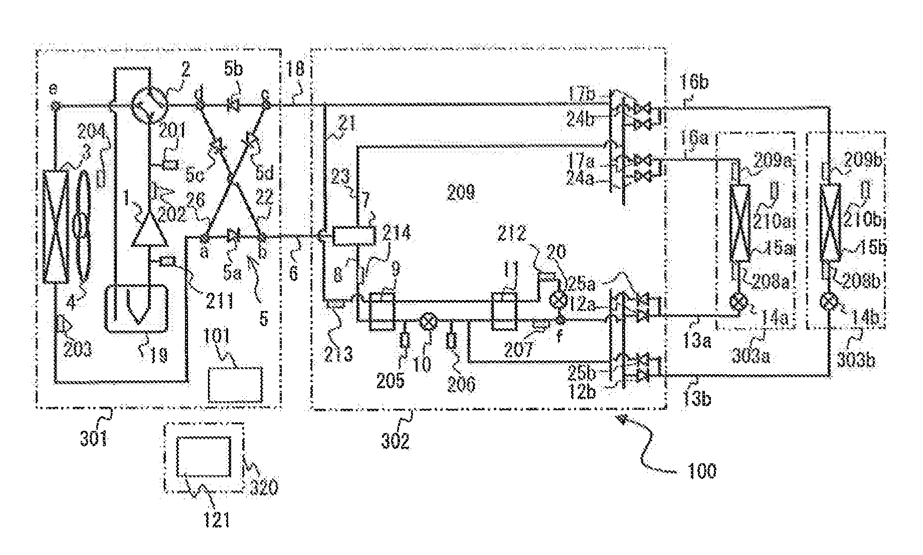
[0022]FIG. 1 is a refrigerant circuit diagram of an air-conditioning apparatus 100 into which a refrigerant is charged using a refrigerant charge assisting device 121 according to the first exemplary embodiment of the present disclosure. This air-conditioning apparatus 100 is installed in office buildings, apartments, and commercial facilities. The air-conditioning apparatus 100 is an apparatus that performs a refrigeration cycle operation by vapor compression in which a refrigerant for air conditioning is circulated. By performing a refrigeration cycle operati...

second exemplary embodiment

[0249]In the first exemplary embodiment described above, description has been given of a configuration in which the present disclosure is applied to a refrigerant circuit that is provided with a relay unit 302 and that is capable of performing a simultaneous cooling and heating operation (a cooling and heating mixed operation), which can perform a cooling or heating operation in each of the use units 303a and 303b. In the second exemplary embodiment, a configuration is set forth in which the present disclosure is applied to a different refrigerant circuit.

[0250]FIG. 9 is a refrigerant circuit diagram illustrating an air-conditioning apparatus 200 according to the second exemplary embodiment of the present disclosure.

[0251]The air-conditioning apparatus 200 is capable of processing a cooling command (cooling ON / OFF) or a heating command (heating ON / OFF) that has been selected in use units 303a and 303b and thus is capable of carrying out cooling or heating. The same components as tho...


PUM


Abstract

Operation data of a refrigerant circuit is acquired after an initial refrigerant charge amount of refrigerant is charged in the refrigerant circuit and operation of the refrigerant circuit is started, an internal volume of a high-pressure pipe 6 is computed from the obtained operation data and the initial refrigerant charge amount input in a input unit 112, a target refrigerant charge amount is computed from the computed internal volume of the high-pressure pipe 6 and a standard operating state acquired in advance, the standard operating state being operation data of the refrigerant circuit when the refrigerant circuit is in a standard operating state that satisfies a preset condition, and an additional refrigerant charge amount is computed from the target refrigerant charge amount and the initial refrigerant charge amount.

Description

TECHNICAL FIELD[0001]The present disclosure relates to a refrigerant charge assisting device, an air-conditioning apparatus, and a refrigerant charge assisting program.BACKGROUND ART[0002]In an air-conditioning apparatus established by connecting a plurality of use units to at least one heat source unit via refrigerant extension pipes, a refrigerant is charged at the time of installation work of the units with the amount according to the length of the refrigerant extension pipes at the installation site. Here, if the charged refrigerant amount is not adequate, a flaw in the operating state of the air-conditioning apparatus will occur. If there is an overcharge, for example, the pressure in the refrigeration cycle apparatus during operation of the device will be high; hence, the device will be forced to be stopped due to safety reasons and will fall into a situation not allowing its operation to be performed. Conversely, if the charged refrigerant amount is insufficient, the intended...

Claims


Application Information

Patent Timeline
IPC IPC(8): F25B45/00
CPCF25B45/00F25B13/00F25B49/022F25B2313/006F25B2313/0231F25B2313/0233F25B2313/02741F25B2313/0311F25B2313/0314F25B2313/0315F25B2345/001F25B2345/003F25B2400/13F25B2500/19F25B2500/23F25B2500/24F25B2600/0253F25B2600/05F25B2700/1931F25B2700/1933F25B2700/2103F25B2700/2104F25B2700/2106F25B2700/21152F25B2400/23Y02B30/70
Inventor TAMAKI, SHOGOUNEZAKI, FUMITAKESHINOZAKI, KAZUYOSHIKASAI, TOMOHIKO
Owner MITSUBISHI ELECTRIC CORP
Why Eureka
Try Eureka