
Liquid processing apparatus, liquid processing method, and storage medium for liquid process

a technology of liquid processing apparatus and liquid processing method, which is applied in the direction of positive displacement liquid engine, cleaning using liquids, machines/engines, etc., can solve problems such as non-uniformity and/or defects, and achieve the effect of reducing throughput, efficiently removing, and reducing throughpu

Active Publication Date: 2014-06-26
TOKYO ELECTRON LTD
View PDF6 Cites 18 Cited by
  • Summary
  • Abstract
  • Description
  • Claims
  • Application Information

AI Technical Summary

Benefits of technology

The present invention provides a liquid processing apparatus that can achieve high filtration efficiency with a single filter without compromising throughput. The apparatus controls the discharge of the process liquid from the filter and the number of circulations to achieve the same efficiency as multiple filters. The remaining process liquid is returned to the primary side of the filter and synthesized by adding a replenishment amount. The discharge of the synthesized process liquid and filtration by the filter are performed the number of times corresponding to a rate between the discharge amount and the return amount. This results in a similar filtration efficiency as using multiple filters without significantly modifying the apparatus. The apparatus can also remove bubbles and efficiently degas the process liquid by discharging a portion from the filter and adding a replenishment amount. This ensures a high-quality process liquid for further use.

Problems solved by technology

When a process liquid containing bubbles or particles mixed therein is supplied to a wafer, application non-uniformity and / or defect may occur.

Method used


Image

  • Liquid processing apparatus, liquid processing method, and storage medium for liquid process
  • Liquid processing apparatus, liquid processing method, and storage medium for liquid process
  • Liquid processing apparatus, liquid processing method, and storage medium for liquid process

Examples


first embodiment

[0092]Embodiments of the present invention will be described herebelow with reference to the accompanying drawings. Herein, there is described an example in which a liquid processing apparatus (resist liquid processing apparatus) according to the present invention is applied to a coating and developing apparatus.

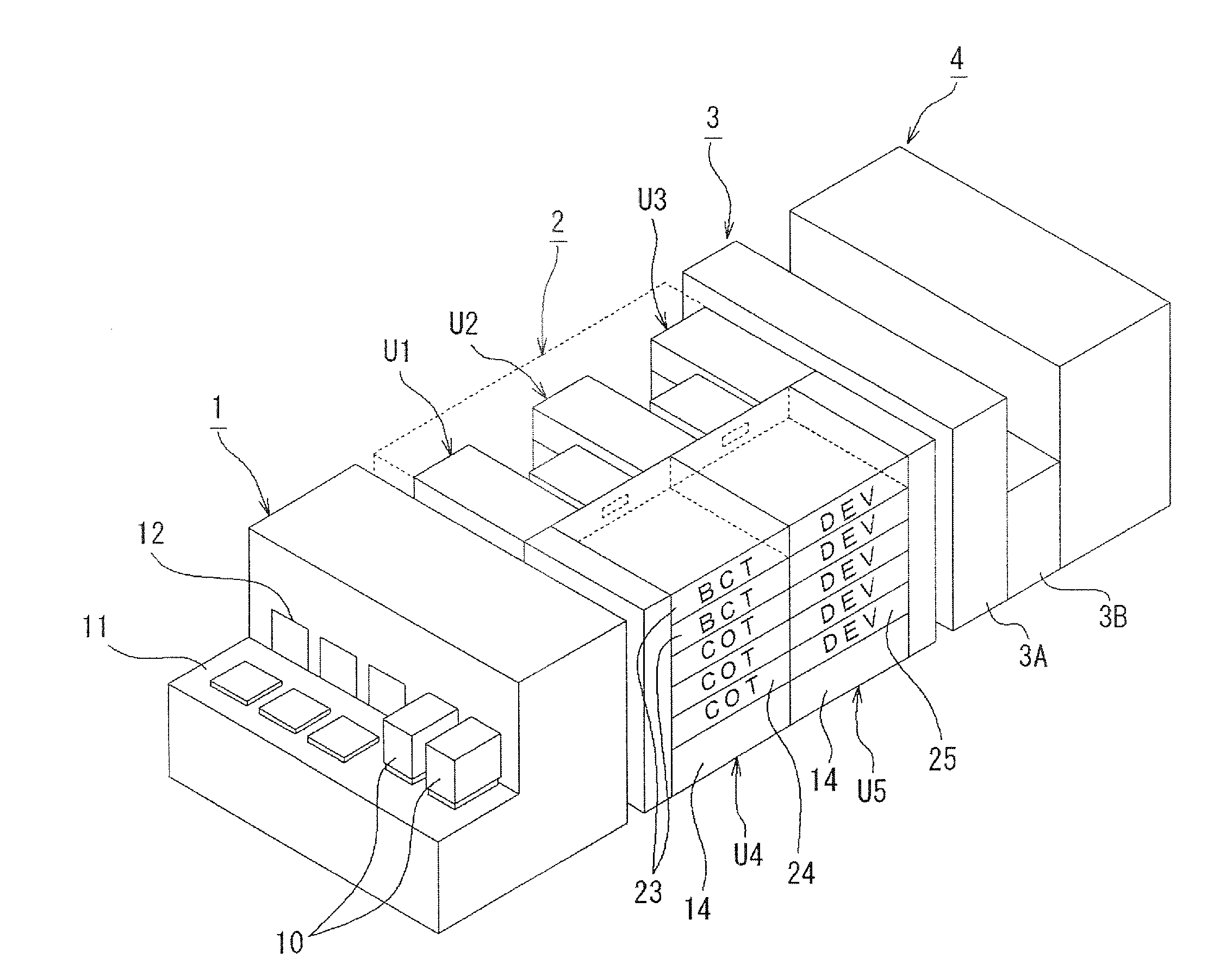
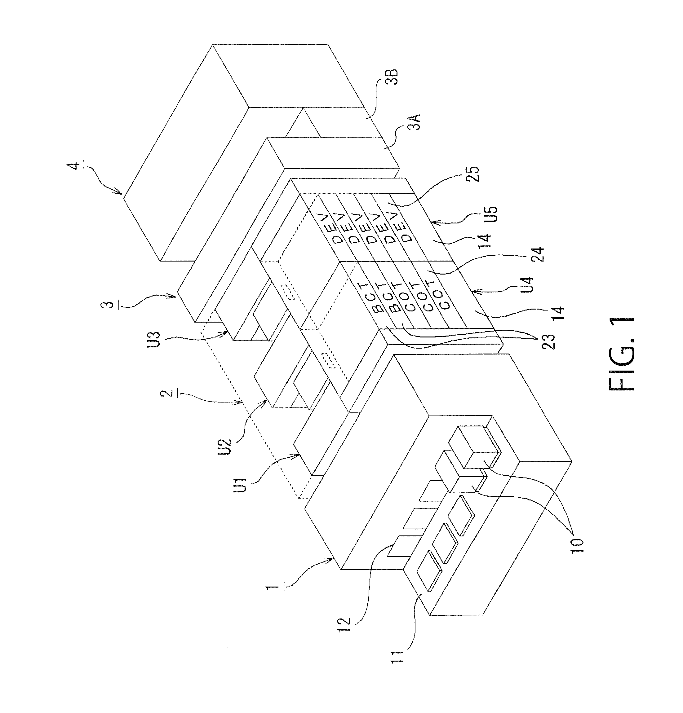
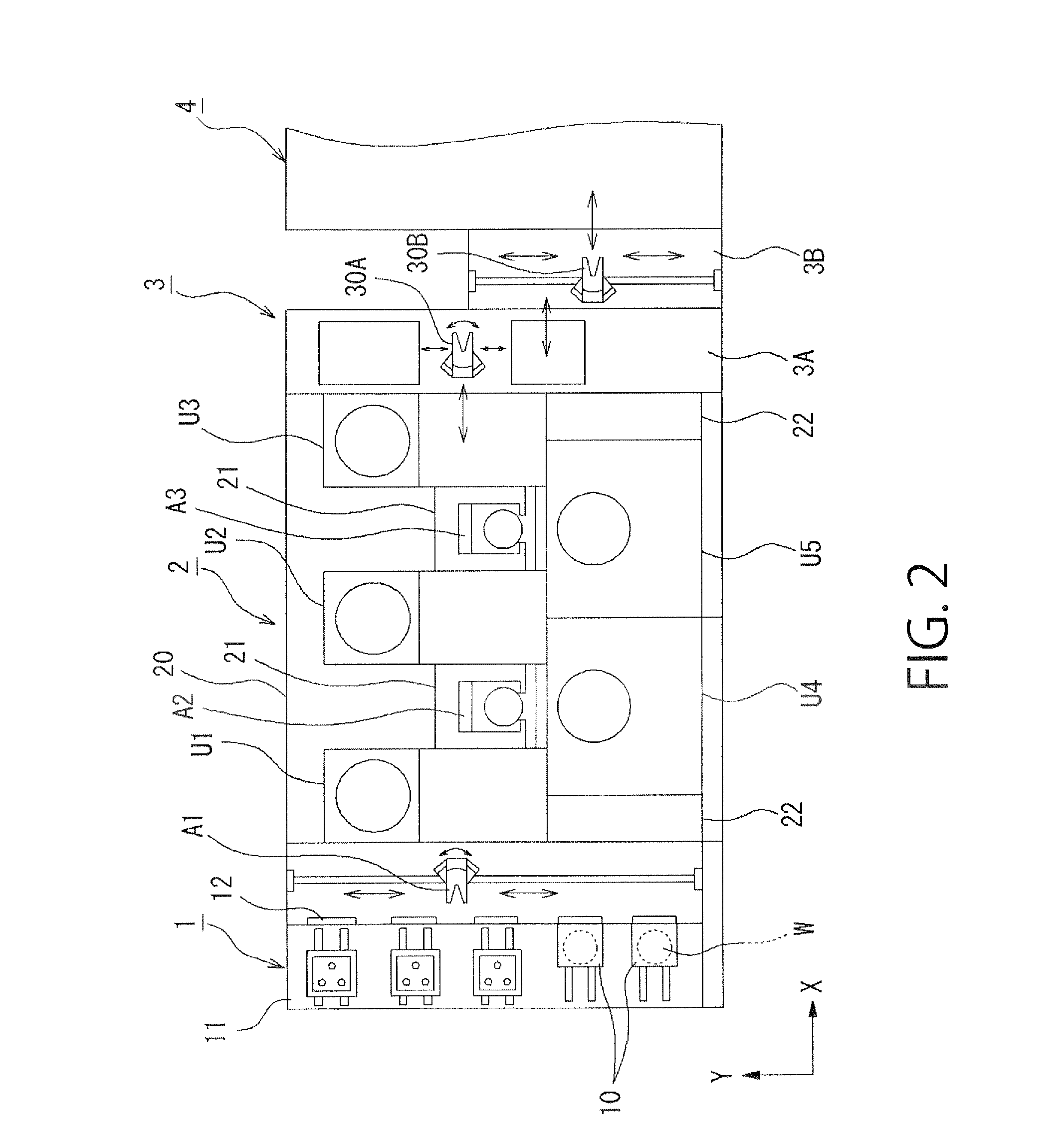
[0093]As shown in FIGS. 1 and 2, the coating and developing apparatus includes: a carrier station 1 through which a carrier 10, which hermetically contains a plurality of, e.g., twenty five wafers W as substrates to be processed, is loaded and unloaded; a processing part 2 configured to perform a resist coating process, a developing process and so on to a wafer W taken out from the carrier station 1; an exposure part 4 configured to immersion-expose a surface of the wafer W with a light-transmitting liquid layer being formed on the surface of the wafer W; and an interface part 3 connected between the processing part 2 and the exposure part 4 and configured to deliver and rec...

4th embodiment

1-4th Embodiment

[0158]A 1-4th embodiment of the liquid processing apparatus according to the present invention is described with reference to FIG. 26. In the 1-4th embodiment, as to the same structure as that of the 1-1st embodiment, the same part is indicated by the same reference number and description thereof is omitted.

[0159]In the 1-4th embodiment, a check valve (not shown) is provided instead of the on-off valve V2 disposed on the connection portion between the diaphragm pump 70 and the third process-liquid supply conduit 51c, and a flowrate regulating valve V6 is disposed in the third process-liquid supply conduit 51c on the secondary side of the connection portion between the third process-liquid supply conduit 51c and the return conduit 55. The flowrate regulating valve V6 is an on-off valve capable of regulating a flow rate of the resist liquid L to be discharged to the discharge nozzle 7.

[0160]In addition, instead of the on-off valve V3 disposed in the connection portion ...

second embodiment

[0166]Herebelow, a second embodiment of the present invention is described with reference to FIGS. 27 to 40. Herein, there is described an example in which the liquid processing apparatus (resist liquid processing apparatus) according to the present invention is applied to a coating and developing apparatus. In the second embodiment, the same part as those of the first embodiment shown in FIGS. 1 to 27 is indicated by the same reference number and description thereof is omitted.

[0167]A 2-1st embodiment of the liquid processing apparatus according to present invention is described.

2-1st Embodiment

[0168]As shown in FIG. 27, the liquid processing apparatus 5 according to the present invention includes: a process liquid container 60 configured to contain a resist liquid L as a process liquid; a discharge nozzle 7 configured to discharge (supply) the resist liquid L to a wafer as a substrate to be processed; a supply conduit 51 connecting the process liquid container 60 and the discharge...


PUM


Abstract

A filtration efficiency, which is similar to the filtration efficiency obtained when a plurality of filters are provided, can be obtained by one filter, and decrease in throughput can be prevented. Based on a control signal from a control unit 101, a resist liquid L is sucked into a pump 70 through a filter. A part of the resist liquid sucked in the pump is discharged from a discharge nozzle 7. The remaining resist liquid is returned to a supply conduit 51b on a primary side of the filter. A process is synthesized by adding a replenishment amount equal to the discharge amount to the return amount. The discharge of the synthesized process liquid and the filtration thereof by the filter are performed the number of times corresponding to a rate between the discharge amount and the return amount.

Description

CROSS REFERENCE TO RELATED APPLICATIONS[0001]This application is based upon and claims the benefit of priority from the prior Japanese Patent Application No. 2012-277600 filed on Dec. 20, 2012, Japanese Patent Application No. 2013-085361 filed on Apr. 16, 2013, Japanese Patent Application No. 2013-206089 filed on Oct. 1, 2013, and Japanese Patent Application No. 2013-206090 filed on Oct. 1, 2013, the entire contents of which are incorporated herein by reference.FIELD OF THE INVENTION[0002]The present invention relates to a liquid processing apparatus, a liquid processing method and a storage medium for liquid process, which are configured to process a surface of a substrate to be processed, such as a semiconductor wafer or a glass substrate for LCD, by supplying thereto a process liquid.BACKGROUND ART[0003]In general, in a photolithographic technique for manufacturing semiconductor devices, a photoresist is applied to a semiconductor wafer or a FPD substrate and the like (hereinafte...

Claims


Application Information

Patent Timeline
Patent Type & Authority Applications(United States)
IPC IPC(8): H01L21/67
CPCH01L21/0274H01L21/67023H01L21/6715F04B43/0081F04B49/065F04B2205/503H01L21/67017H01L21/302
Inventor TAKAYANAGI, KOJIMINEKAWA, YUKIEYOSHIDA, YUICHIYOSHIHARA, KOUSUKETERASHITA, YUICHIFURUSHO, TOSHINOBUSASA, TAKASHI
Owner TOKYO ELECTRON LTD
Learn More