Hydrogen/oxygen generator apparatus and system
- Summary
- Abstract
- Description
- Claims
- Application Information
AI Technical Summary
Benefits of technology
Problems solved by technology
Method used
Image

Examples
Embodiment Construction
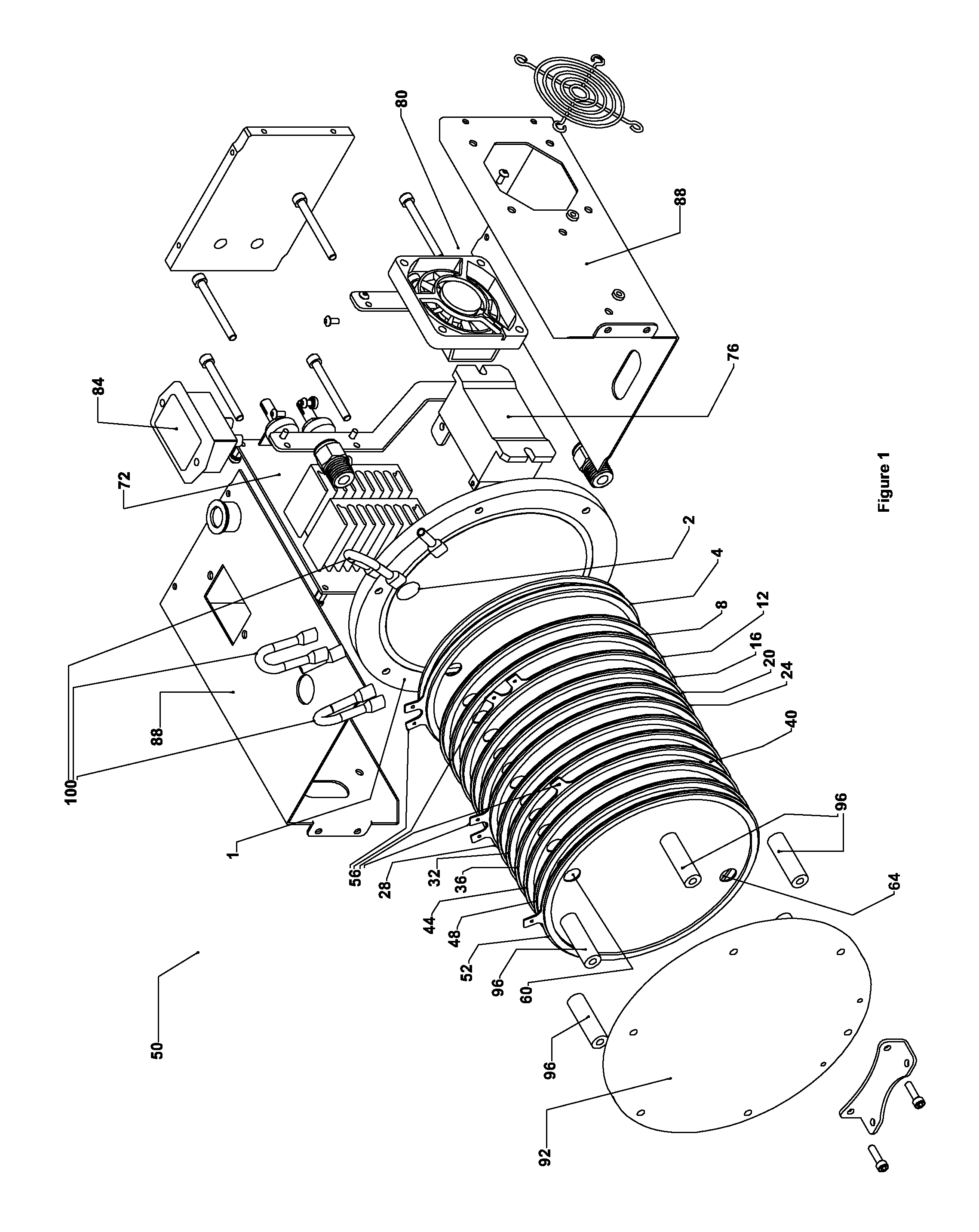
[0014]FIG. 1 shows an exploded view of the hydrogen / oxygen generator 50. An inlet plate 1 is adjacent to a first cathode plate 4. The inlet plate has a first hole 2 and a second hole 3. The holes 2, 3 may each be configured to thread onto a tube fitting, and the tube fitting may be attachable to a hose (not shown). A hose in communication with hole 2 may be an oxygen and hydrogen carrying hose. And a hose in communication with hole 3 may be an electrolytic fluid carrying hose. The first hole 2 is located generally near the top of the plate, and the second hole 3 (not visible in this view) is located generally near the bottom of the plate. A first diaphragm plate 8 and second diaphragm plate 12 are located between the first cathode plate 4 and a first anode plate 16. A third diaphragm plate 20 and fourth diaphragm plate 24 are located between the first anode plate 16 and a second cathode plate 28. A fifth and sixth diaphragm plate 32, 36 are located between the second cathode plate 2...
PUM
| Property | Measurement | Unit |
|---|---|---|
| Pressure | aaaaa | aaaaa |
| Electrical conductor | aaaaa | aaaaa |
| Frequency | aaaaa | aaaaa |
Abstract
Description
Claims
Application Information
 - Generate Ideas
- Intellectual Property
- Life Sciences
- Materials
- Tech Scout
- Unparalleled Data Quality
- Higher Quality Content
- 60% Fewer Hallucinations
Browse by: Latest US Patents, China's latest patents, Technical Efficacy Thesaurus, Application Domain, Technology Topic, Popular Technical Reports.
© 2025 PatSnap. All rights reserved.Legal|Privacy policy|Modern Slavery Act Transparency Statement|Sitemap|About US| Contact US: help@patsnap.com