Radiation enhanced resistive switching layers

a resistive switching and radiation enhancement technology, applied in the field of semiconductor devices and processes, can solve the problems of difficult to form conductive paths, difficult to control these techniques, inconsistent performance, etc., and achieve the effect of improving the resistive switching characteristics and lowering the switching voltage and/or curren

Inactive Publication Date: 2014-06-26
SANDISK TECH LLC +2
View PDF2 Cites 5 Cited by
  • Summary
  • Abstract
  • Description
  • Claims
  • Application Information

AI Technical Summary

Benefits of technology

[0005]Provided are radiation enhanced resistive switching layers, resistive random access memory (ReRAM) cells including these layers, as well as methods of forming these layers and cells. Radiation creates defects in resistive switching materials that allow forming and breaking conductive paths in these materials thereby improving their resistive switching characteristics. For example, ionizing radiation may break chemical bonds in various materials used for such a layer, while non-ionizing radiation ma

Problems solved by technology

These defects are typically introduced during fabrication of ReRAM cells using various techniques, such as doping of resistive switching materials or extracting some materials from resistive switching layers (e.g., trapping oxygen to form oxygen vacancies).
However, many of these techniques are hard to control.
Defects may be provided at inconsistent concentrations and distributions within resistive switching layer causing inconsistent performance.
For example, inadequate amounts of defects make it difficult to form conductive paths, while excessive levels may make it difficult to break these conductive paths.
Furthermore, different types of defects result in different resistive switching characteristics.
Another major problem that appears with many conventional defect generating techniques is caused by random and often inconsistent distribution of defects, which makes it difficult to control location and levels of conductive path formation.
Subsequent irradiation creates defects in a controlled manner, e.g., by supplying radiation at a certain power, doze, and/or location.
For example, defects may be unevenly distributed throughout the thickness of the resistive switching layer, i.e., in the direction along the height of the stack.
For example, doping or oxygen trapping makes i

Method used


Image

  • Radiation enhanced resistive switching layers
  • Radiation enhanced resistive switching layers
  • Radiation enhanced resistive switching layers

Examples


Embodiment Construction

[0018]A detailed description of various embodiments is provided below along with accompanying figures. The detailed description is provided in connection with such embodiments, but is not limited to any particular example. The scope is limited only by the claims and numerous alternatives, modifications, and equivalents are encompassed. Numerous specific details are set forth in the following description in order to provide a thorough understanding. These details are provided for the purpose of example and the described techniques may be practiced according to the claims without some or all of these specific details. For the purpose of clarity, technical material that is known in the technical fields related to the embodiments has not been described in detail to avoid unnecessarily obscuring the description.

INTRODUCTION

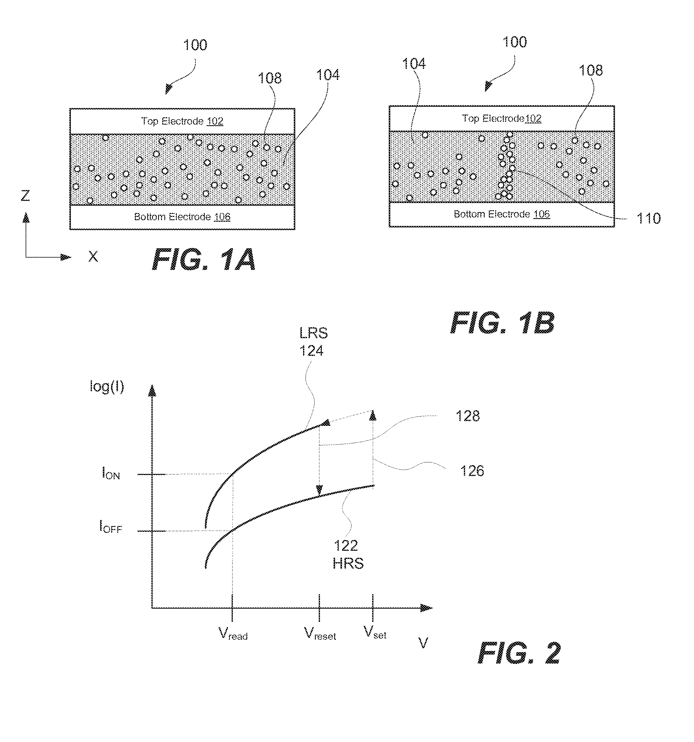
[0019]A ReRAM cell exhibiting resistive switching characteristics generally includes multiple layers formed into a stack. The structure of this stack is sometimes desc...


PUM


Abstract

Provided are radiation enhanced resistive switching layers, resistive random access memory (ReRAM) cells including these layers, as well as methods of forming these layers and cells. Radiation creates defects in resistive switching materials that allow forming and breaking conductive paths in these materials thereby improving their resistive switching characteristics. For example, ionizing radiation may break chemical bonds in various materials used for such a layer, while non-ionizing radiation may form electronic traps. Radiation power, dozing, and other processing characteristics can be controlled to generate a distribution of defects within the resistive switching layer. For example, an uneven distribution of defects through the thickness of a layer may help with lowering switching voltages and/or currents. Radiation may be performed before or after thermal annealing, which may be used to control distribution of radiation created defects and other types of defects in resistive switching layers.

Description

TECHNICAL FIELD[0001]The present invention relates generally to semiconductor devices and processes and, more specifically, to radiation enhanced resistive switching layers and resistive random access memory (ReRAM) cells containing these layers and methods of fabricating thereof.BACKGROUND[0002]Nonvolatile memory is computer memory capable of retaining the stored information even when unpowered. Non-volatile memory may be used for secondary storage or long-term persistent storage, for example, in addition to volatile memory. Nonvolatile memory can be permanently integrated into computer systems (e.g., solid state hard drives) or it can take the form of removable and easily transportable memory cards (e.g., USB flash drives). Nonvolatile memory is becoming more popular because of its small size and high density, low power consumption, fast read and write rates, data retention, and other characteristics.[0003]Flash memory is a common type of nonvolatile memory because of its high den...

Claims


Application Information

Patent Timeline
IPC IPC(8): H01L45/00
CPCH01L45/08H01L45/1641H01L27/2463H01L45/1253H01L45/16H01L45/146H10B63/80H10N70/24H10N70/841H10N70/8833H10N70/041
Inventor WANG, YUNCHIANG, TONY P.MINVIELLE, TIMYAMAGUCHI, TAKESHI
Owner SANDISK TECH LLC
Why Eureka
Try Eureka