Motor controller and brushless DC motor comprising the same

a motor controller and dc motor technology, applied in the direction of dynamo-electric machines, cooling/ventilation/heating modifications, conduction heat transfer modifications, etc., can solve the problems of motor short circuit, poor insulating effect, structure danger of electrical leakage, etc., to achieve good insulating effect, simple structure, and convenient assembly

Active Publication Date: 2014-06-26
ZHONGSHAN BROAD OCEAN
View PDF4 Cites 7 Cited by
  • Summary
  • Abstract
  • Description
  • Claims
  • Application Information

AI Technical Summary

Benefits of technology

[0007]In view of the above-described problems, it is one objective of the invention to provide a motor controller and a brushless DC motor comprising the same. The motor controller comprises an IGBT module which is isolated safely, thereby effectively solving the problems of potential danger of electrical leakage of the controller and has a good insulating effect. The brushless DC motor of the invention effectively solves problems of water proof and drainage, and also has a simple structure, convenient assembly, and good waterproof and drainage performance.

Problems solved by technology

Such a structure has a potential danger of electrical leakage and a poor insulating effect.
However, when the motor is applied to an outdoor unit of an air-conditioner, the seal washer easily ages, and water easily penetrates into the motor and is difficult to be drained out, which results in short circuit of the motor and poor waterproof and drainage performance

Method used


Image

  • Motor controller and brushless DC motor comprising the same
  • Motor controller and brushless DC motor comprising the same
  • Motor controller and brushless DC motor comprising the same

Examples


example 1

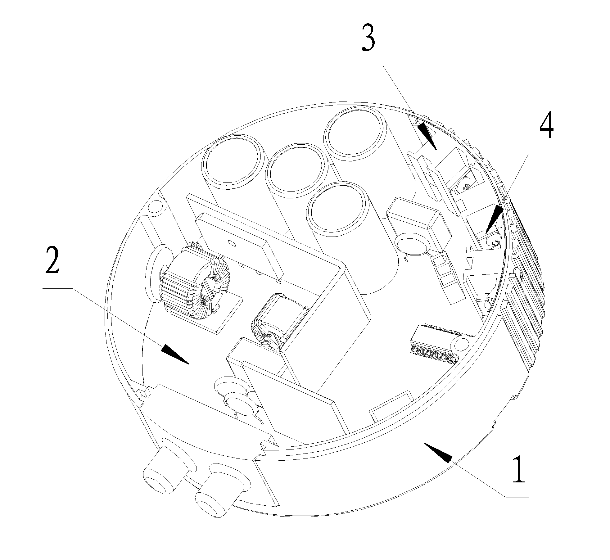
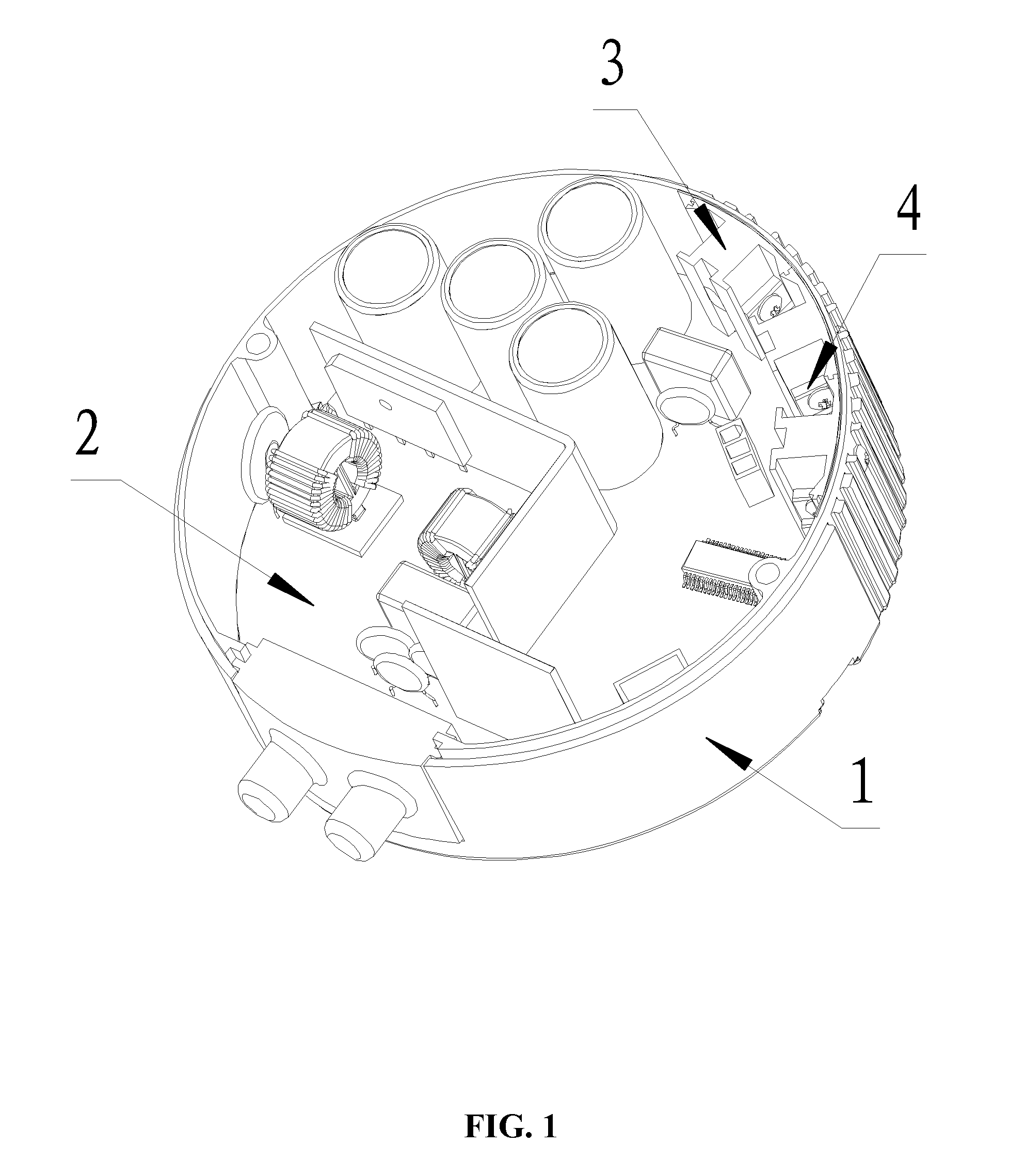
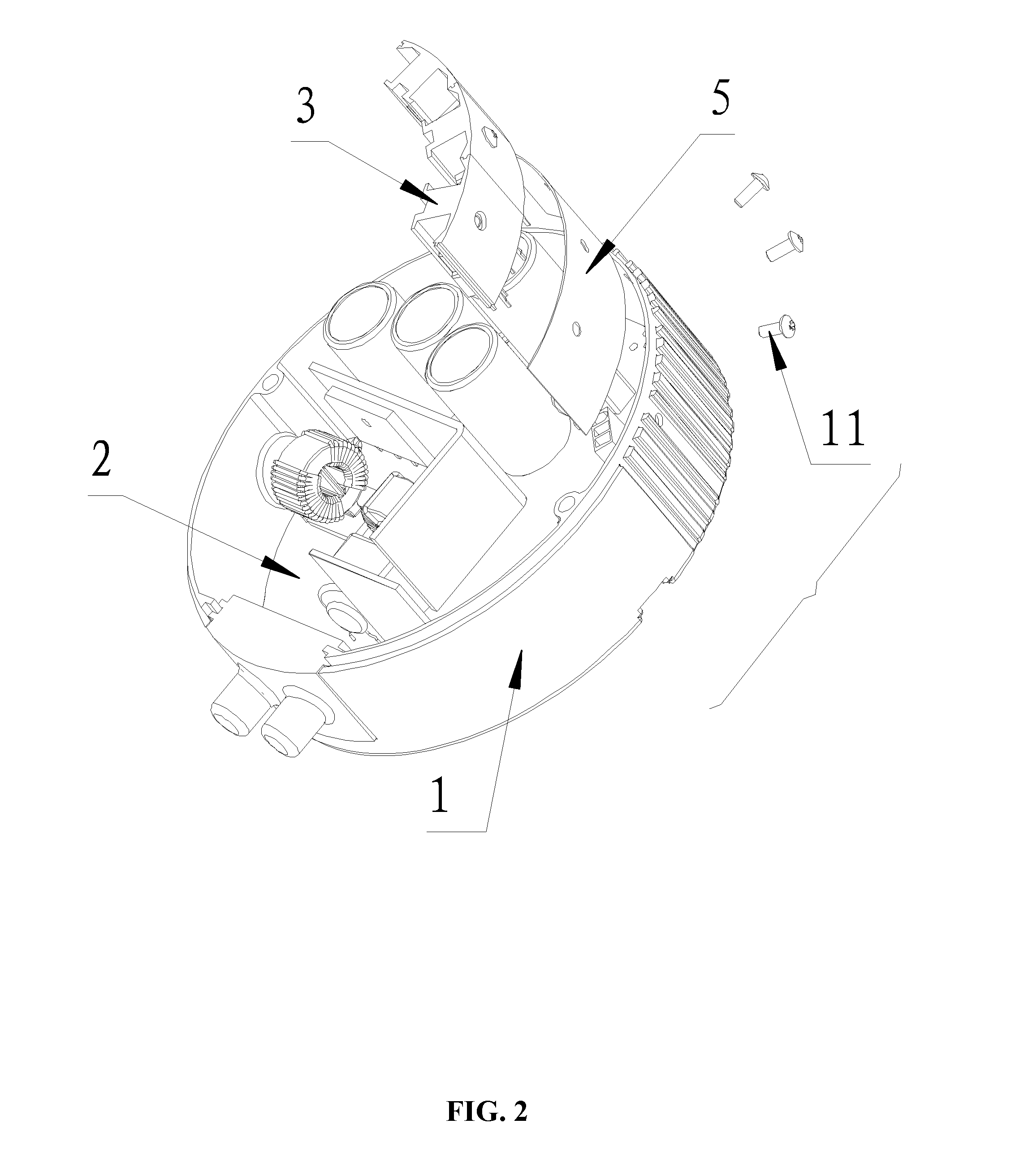
[0040]As shown in FIGS. 1-4 and 7-8, a motor controller, comprises: a control box 1, a circuit board 2, a dissipater 3, and an IGBT module 4. The circuit board 2 is disposed inside the controller box 1, and the dissipater 3 is disposed on an inner wall of the control box 1. The IGBT module 4 is disposed on the dissipater 3 and is in electric connection with the circuit board 2. The insulating piece 5 is disposed between the dissipater 3 and the controller 1 and prevents the dissipater 3 from contacting with the control box 1.

[0041]The dissipater 3 is provided with a mounting hole 31. An insulting bush 32 is disposed inside the mounting hole 31. A first screw 11 passes through the control box 1 and the insulating piece 5 and is embedded inside the insulating bush 32 for locking the dissipater 3.

[0042]The insulating bush 32 comprises two ends. A first end of the insulating bush 32 is provided with a step 321, and the step 321 is locked on an outer wall of the dissipater 3. A second en...

example 2

[0048]The motor controller of Example 2 is the same as that in Example 1 except that the insulating bush 32 is formed inside the mounting hole 31 of the dissipater 3 by injection molding.

[0049]As shown in FIGS. 1-2, 5-6, and 8, a motor controller, comprises: a control box 1, a circuit board 2, a dissipater 3, and an IGBT module 4. The circuit board 2 is disposed inside the controller box 1, and the dissipater 3 is disposed on an inner wall of the control box 1. The IGBT module 4 is disposed on the dissipater 3 and is in electric connection with the circuit board 2. The insulating piece 5 is disposed between the dissipater 3 and the controller 1 and prevents the dissipater 3 from contacting with the control box 1.

[0050]The dissipater 3 is provided with a mounting hole 31. An insulting bush 32 is disposed inside the mounting hole 31. A first screw 11 passes through the control box 1 and the insulating piece 5 and is embedded inside the insulating bush 32 for locking the dissipater 3.

[...

example 3

[0057]As shown in FIG. 9-14, a brushless DC motor, comprises: a housing 6, a stator assembly 7, a rotor assembly 8, a front-end cover 9, a rear-end cover 10, a control box 1, a circuit board 2, a dissipater 3, a IGBT module 4, and an insulating piece 5. The stator assembly 7 is disposed inside the housing 6. The rotor assembly 8 is disposed on a bearing of the front-end cover 9 and the rear-end cover 10 and is inserted into the stator assembly 7. The front-end cover 9 and the rear-end cover 10 are disposed on two ends of the housing 6, respectively. The circuit board 2 is arranged inside the control box 1. The dissipater 3 is disposed on the inner wall of the control box 1. The IGBT module 4 is disposed on the dissipater 3 and is in electric connection with the circuit board 2. A plurality of positioning holes 12 are disposed on the control box 1; and a plurality of threaded holes 101 are disposed on the rear-end cover 10. A screw bar 102 passes through each positioning hole 101 and...


PUM


Abstract

A motor controller, including: a control box including an inner wall; a circuit board; a dissipater; an IGBT module; and an insulating piece. The circuit board is disposed inside the controller box. The dissipater is disposed on the inner wall of the control box. The IGBT module is disposed on the dissipater and is in electric connection with the circuit board. The insulating piece is disposed between the dissipater and the controller and prevents the dissipater from contacting with the control box.

Description

CROSS-REFERENCE TO RELATED APPLICATIONS[0001]This application is a continuation-in-part of International Patent Application No. PCT / CN2012 / 082683 with an international filing date of Oct. 10, 2012, is also a continuation-in-part of International Patent Application No. PCT / CN2012 / 082684 with an international filing date of Oct. 10, 2012, and is also a continuation-in-part of International Patent Application No. PCT / CN2012 / 082644 with an international filing date of Oct. 9, 2012, all designating the United States, all now pending, and further claims foreign priority benefits to Chinese Patent Application No. 201120566281.9 filed Dec. 29, 2011, to Chinese Patent Application No. 201120564259.0 filed Dec. 29, 2011, and to Chinese Patent Application No. 201220193192.9 filed Apr. 28, 2012. The contents of all of the aforementioned applications, including any intervening amendments thereto, are incorporated herein by reference. Inquiries from the public to applicants or assignees concerning...

Claims


Application Information

Patent Timeline
Patent Type & Authority Applications(United States)
IPC IPC(8): H02K11/00H02G3/08H05K7/20
CPCH02K11/0073H05K7/2039H02G3/088H02K11/33H05K7/209
Inventor WU, YONGHUACHEN, YUNSHENGZHAO, YONGZENG, CHONGSHENGTANG, SONGFA
Owner ZHONGSHAN BROAD OCEAN
Why Eureka
Try Eureka