Heat engine with linear actuators

Active Publication Date: 2014-06-26
DAVIS BRIAN
View PDF27 Cites 1 Cited by
  • Summary
  • Abstract
  • Description
  • Claims
  • Application Information

AI Technical Summary

Benefits of technology

[0048]According to one advantage of the present invention, the engine utilizes an elongated driving force due to opening of a valve when one of three apexes passes a prior exhaust port and the expansion chamber volume is small. The faces of the rotor are smooth and undished in order to minimize the volume in each chamber when the valve first opens.
[0049]According to another advantage of the present invention, the input valve can be closed at the appropriate timing whereby pressure in the expansion chamber and the pressure in the system outside of the expansion chamber will be approximately equal when the rotor leading apex passes the exhaust port. In this regard, the efficiency of the expansion phase is maximized because all of the energy is utilized as the pressures are equalized when the system opens to the exhaust.
[0050]According to further advantage of the present invention, the use of valves prevents blow-by in the system. Blow-by would otherwise occur in a system having three apexes of a triangular rotor and two inlets and two exhaust ports spaced about an engine housing since at times in the revolution of the rotor a chamber would be open to both an inlet and an exhaust por

Problems solved by technology

This results in higher combustion efficiencies, lower combustion temperatures and lower rates of production of pollutants such as NO.sub.x.
Due to the geometry of adding a second inlet and exhaust ports, modified engines suffer from blow-by at certain times. The blow-by occurs as an expansion chamber will be open to both the inlet and exhaust simul

Method used


Image

  • Heat engine with linear actuators
  • Heat engine with linear actuators
  • Heat engine with linear actuators

Examples


Example

[0150]A first embodiment can be viewed by looking at FIGS. 1-28.

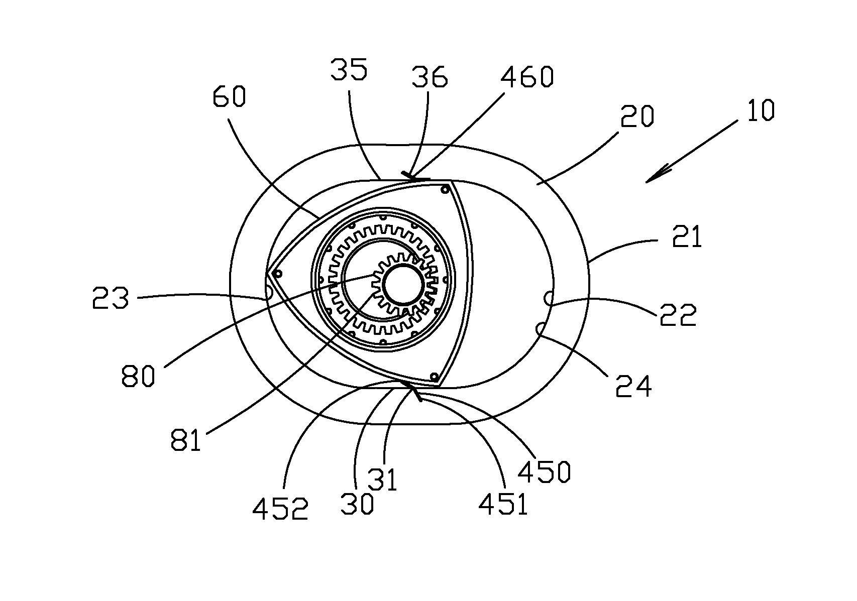
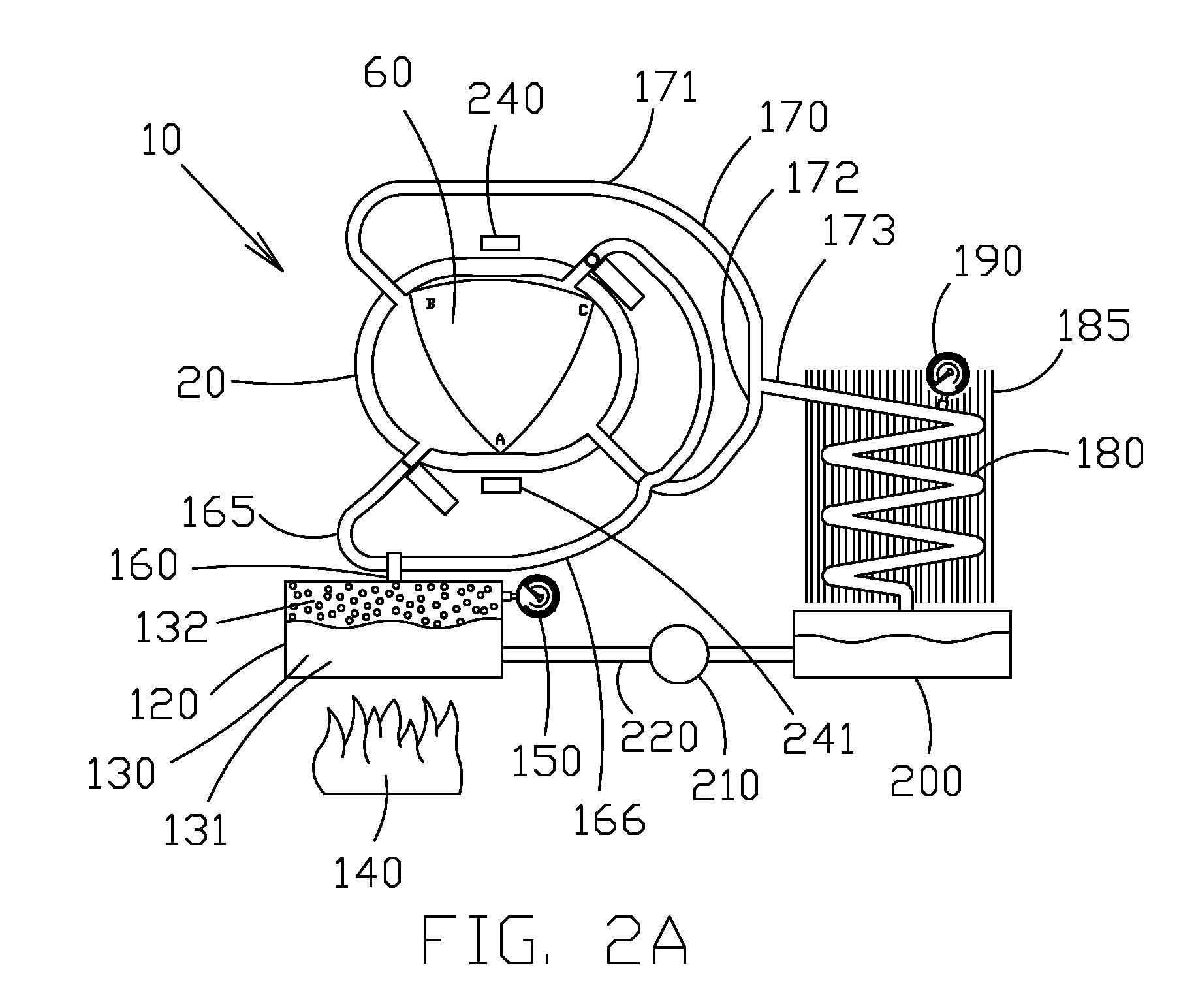
[0151]Looking now to FIG. 2A, it is seen that an engine 10 is provided having a housing 20. A rotor 60 is further provided. The rotor 60 rotates within the housing 20 as described below.

[0152]A high pressure tank 120 is provided. The tank can be any suitable size. The tank 120 can hold a selected amount of working medium 130. The working medium is preferably a commonly available refrigerant that undergoes a phase change between liquid 131 and gas 132 at predictable temperatures and pressures. One preferred refrigerant is R-123. However it is understood that other refrigerants could be used without departing from the broad aspects of the present invention.

[0153]A heat source 140 is provided. The heat source 140 is in close proximity to tank 120, whereby the heat source can heat the working medium 120 causing selected amounts of liquid 131 to undergo a phase change to gas 132. The tank can hold the gas at high pressures. ...


PUM


Abstract

The present invention relates to a heat engine having shafts with gears, position gears and a plurality of actuators. Energy is harnessed from the first shaft as it rotates. The second shaft can be coupled to the first shaft to transfer energy from the second shaft to the first shaft. One coupler is a chain. Position gears orient the chain wherein the rotation of the second shaft is inverted upon the first shaft so that the first shaft has a constant rotational orientation. Each actuator is preferably a double acting actuator that can supply force to both push and pull upon a belt connected to the actuator rod. A 1-way clutch and gear connects the belt to each shaft wherein the belt (driven by actuator) imparts a positive force upon the first shaft on the out stroke and a positive force upon the second shaft on the return stroke.

Description

[0001]This United States utility patent application claims priority on and the benefit of provisional application 61 / 772,740 filed Mar. 5, 2013, the entire contents of which are hereby incorporated herein by reference.[0002]This patent application is a continuation-in-part application of application Ser. No. 13 / 469,306 filed on May 11, 2012, which itself claims priority on and the benefit of U.S. provisional application 61 / 485,849 filed May 13, 2011, the entire contents of both being hereby incorporated herein by reference.BACKGROUND OF THE INVENTION[0003]1. Field of the Invention[0004]The present invention relates to a heat engine, and in particular in one embodiment to a rotary style heat engine and in another embodiment to a linear drive heat engine that can have any number of independent cylinders and one way clutches.[0005]2. Description of the Related Art[0006]Heat energy, sometimes called thermal energy, is defines as the kinetic energy of a system's particles. Put another wa...

Claims


Application Information

Patent Timeline
IPC IPC(8): F01C1/107
CPCF01C1/22F02G1/043F01B1/00F01C21/18
Inventor DAVIS, BRIAN
Owner DAVIS BRIAN
Why Eureka
Try Eureka