Layer system, energy store, and method for manufacturing an energy store

a technology of energy storage and layer system, which is applied in the direction of sustainable manufacturing/processing, non-aqueous electrolyte cells, cell components, etc., can solve the problems of limited power level and associated environmental problems of electrolytes, and achieve the effect of improving stability of layer system, low stability, and reducing the height of layer system according to the present invention

Active Publication Date: 2014-06-26
ROBERT BOSCH GMBH
View PDF6 Cites 16 Cited by
  • Summary
  • Abstract
  • Description
  • Claims
  • Application Information

AI Technical Summary

Benefits of technology

[0033]Within the scope of another exemplary embodiment of the present invention, the side of the top electrode layer and / or of the bottom electrode layer facing the electrolyte layer, and / or the electrolyte layer itself, may be at least partially structured. In this regard, structuring may in turn be formed in particular by a topography such as a comb structure, or some other structure which enlarges the active surface. In this exemplary embodiment it is thus possible to obtain enlarged transition surfaces between the individual functional layers, as the result of which the power of the layer system according to the present invention, for example as an energy store, may be improved.
[0034]It is also preferred for the layer system to include a substrate on which the bottom electrode layer is situated. The substrate may impart improved stability to the layer system, in particular for the case that the individual layers have low stability. This may be the case, for example, as the result of forming very thin layers. The substrate may be formed, for example, from rigid and in particular structurable materials, for example semiconductor materials such as silicon, which are used, for example, for rear sides of active elements such as integrated circuits, microsystem engineering components, or solar cells. Alternatively, flexible substrates may also be used which allow the subsequent introduction of such thin-layer batteries into microsystems such as smart cards, or which also allow scaling to macroscopic energy stores. However, the substrate material should have suitable properties, such as thermal resistance to soldering operations.
[0035]In this regard it may be particularly preferred for the side of the substrate facing the bottom electrode layer to be at least partially structured. Structuring of the substrate may be achieved, for example, by forming caverns in the substrate, or by a comb structure. Thus, in particular the height of the layer system according to the present invention may be reduced, and thus the compactness may be increased. An application in particular in small portable devices as energy stores, for example, may thus be further improved.
[0036]Within the scope of another advantageous exemplary embodiment of the layer system according to the present invention, a current collector layer is situated on the side of the bottom electrode layer and / or the top electrode layer opposite from the electrolyte layer. The current collector layer is used to improve the electrical conductivity of the corresponding electrode layer, and also to provide a suitably establishable contact of the electrode layer. For example, the current collector layer may be made of gold, platinum, aluminum, alloys, or other materials having good electrical conductivity.
[0037]Moreover, the present invention relates to an energy store which includes a layer system according to the present invention. In particular in an energy store, the mentioned advantages such as long service life and enhanced capacity and power are realized in a particularly advantageous manner.

Problems solved by technology

However, the power levels have usually been limited due to the low quantities of active material in the thin two-dimensional layers.
In addition, many electrolytes are associated with environmental problems.

Method used


Image

  • Layer system, energy store, and method for manufacturing an energy store
  • Layer system, energy store, and method for manufacturing an energy store
  • Layer system, energy store, and method for manufacturing an energy store

Examples


Embodiment Construction

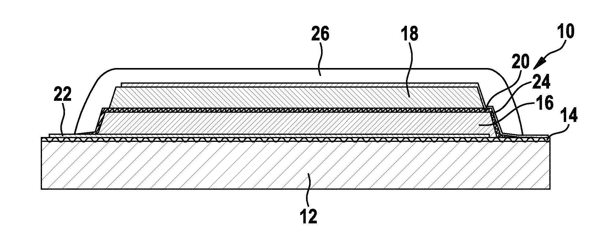
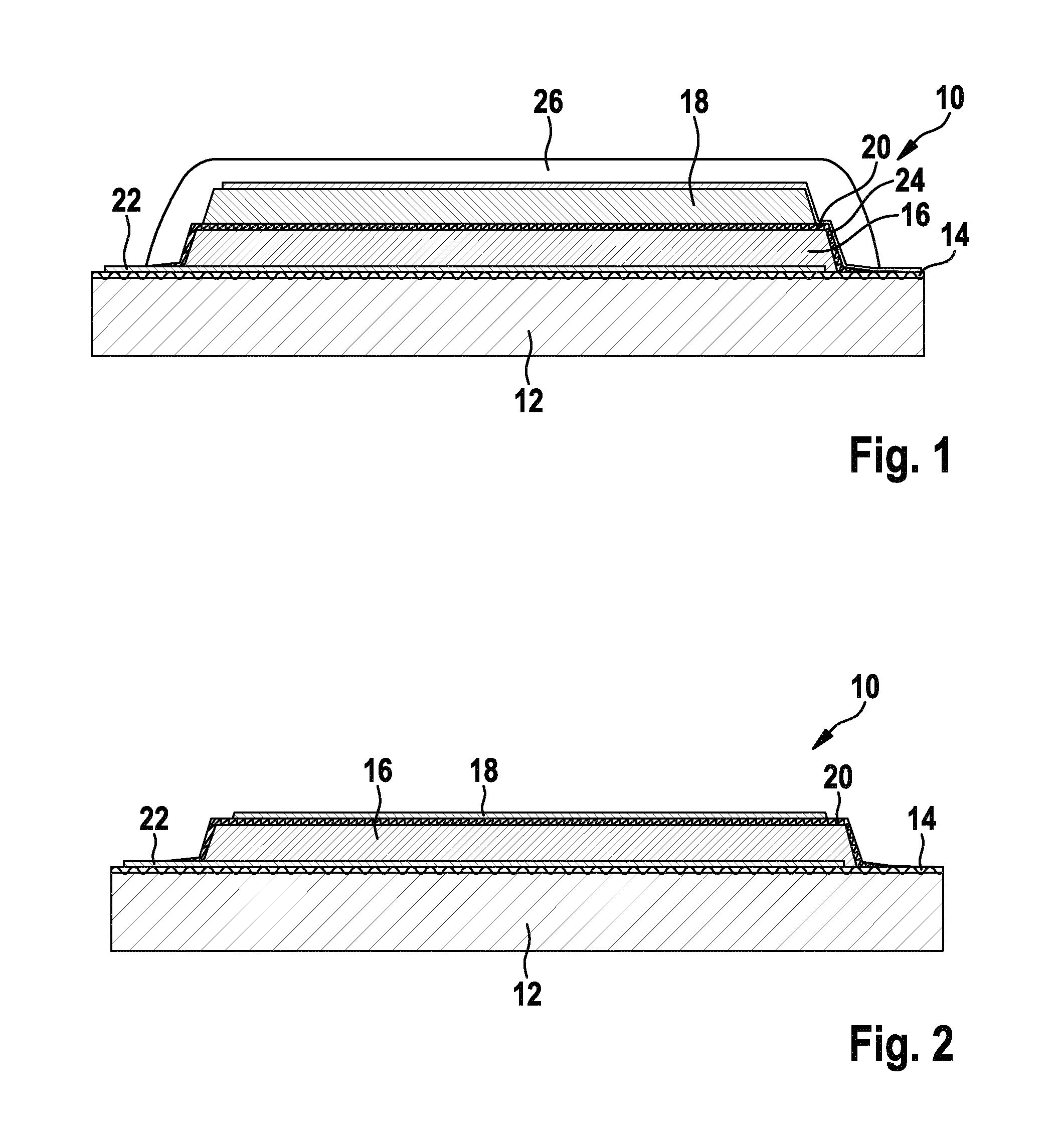
[0055]FIG. 1 shows one exemplary embodiment of layer system 10 according to the present invention. Layer system 10 may, for example, be part of an energy store, a lithium-ion accumulator, for example, or may form same.

[0056]Layer system 10 according to the present invention may include a substrate 12 as a carrier. For this purpose, substrate 12 may be used to impart more stability to the layers. However, substrate 12 is only optional and does not necessarily have to be present. For example, substrate 12 may be dispensed with if the layers have sufficient stability. Substrate 12 is formed, for example, from a semiconductor material or MEMS material such as silicon or glass. In addition, substrate 12 may be made of a polymer or a metal. It is advantageous for the surface of substrate 12 to be electrically insulating. For this purpose, an insulating layer 14 may be provided on substrate 12 if the material of the substrate is not electrically insulating per se. For example, this insulat...


PUM

PropertyMeasurementUnit
thicknessesaaaaaaaaaa
electrical conductivityaaaaaaaaaa

Abstract

A layer system includes at least three layers, the three layers including a top electrode layer, a bottom electrode layer, and an electrolyte layer situated between the top electrode layer and the bottom electrode layer. The electrolyte layer has a solid-state electrolyte, and at least one of the top and bottom electrode layers includes a paste-like composite layer. A layer system of this type may be used to manufacture in particular energy stores, such as rechargeable lithium-ion accumulators, having an enhanced capacity. Moreover, a method for producing a layer system or an energy store is described.

Description

CROSS REFERENCE TO RELATED APPLICATION[0001]The present application is the national stage entry of International Patent Application No. PCT / EP2012 / 054856, filed on Mar. 20, 2012, which claims priority to Application No. DE 10 2011 076 177.2, filed in the Federal Republic of Germany on May 20, 2011.FIELD OF INVENTION[0002]The present invention relates to a layer system, an energy store which includes the layer system, and a method for producing a layer system. The present invention relates in particular to a lithium-ion accumulator having enhanced capacity.BACKGROUND INFORMATION[0003]Lithium-ion batteries and lithium-ion accumulators are widely used nowadays. They are preferably used in particular in portable devices such as mobile telephones or mobile computers. Their advantages lie in particular in their high power density and capacity density. Attempts have previously been made to manufacture lithium ion accumulators with the aid of semiconductor processes in thin layer technology...

Claims


Application Information

Patent Timeline
Patent Type & Authority Applications(United States)
IPC IPC(8): H01M4/62H01M4/04
CPCH01M4/0404H01M10/052H01M4/62H01M10/058Y02E60/122H01M10/0562Y02E60/10Y02P70/50
Inventor PIRK, TJALFMOERSCH, GILBERTSCHECKER, OLIVER
Owner ROBERT BOSCH GMBH
Why Eureka
Try Eureka