Aortic artery measuring probe, device and method of measuring diameter of aortic artery
a technology of aortic artery and measuring probe, which is applied in the field of measuring probe, aortic artery measuring device, and measuring method of aortic artery diameter, can solve the problems of low examination cost, high examination cost of ct and nmri, and difficulty in interpreting images, so as to achieve more flexibility in the preferred examination method
- Summary
- Abstract
- Description
- Claims
- Application Information
AI Technical Summary
Benefits of technology
Problems solved by technology
Method used
Image
Examples
first embodiment
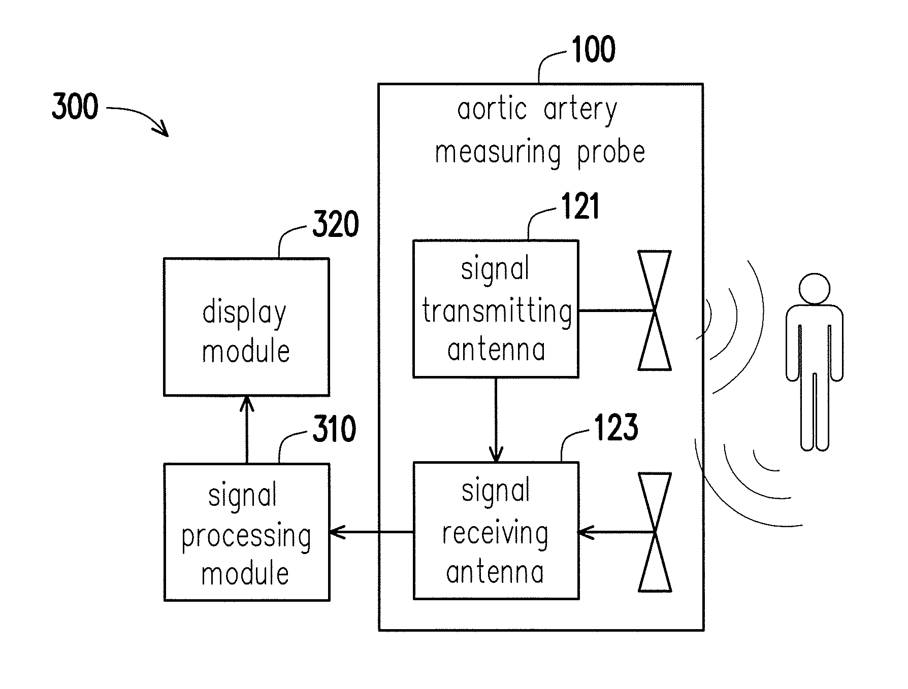
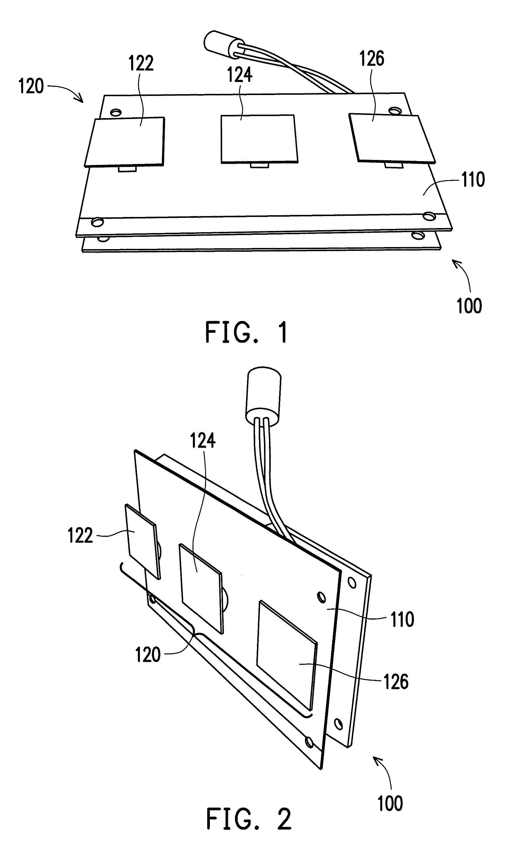
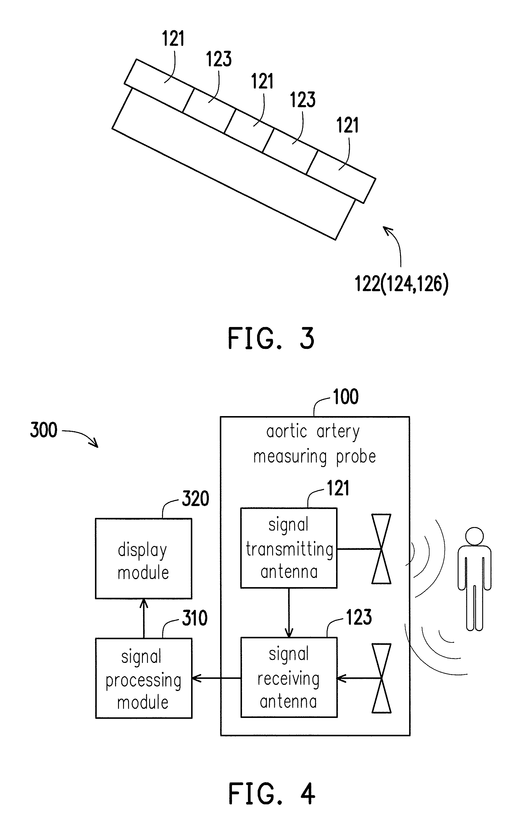
[0036]FIGS. 1 and 2 are schematic views at different angles of an aortic artery measuring probe according to a first embodiment of the disclosure, and FIG. 3 is a schematic view of an ultra-wideband sensor. With reference to FIGS. 1, 2, and 3, the disclosure provides an aortic artery measuring probe 100, including a flexible substrate 110 and a sensor array 120 disposed on the flexible array 110. The sensor array 120 has M×N ultra-wideband sensors, and in the present embodiment, M is 1 and N is 3. The ultra-wideband sensors 122, 124, and 126 are positioned on a to-be-measured subject 200 (as shown in FIG. 7). In this exemplary embodiment, the ultra-wideband sensors 122, 124, and 126 are positioned on the to-be-measured subject 200 and focused on the target aortic artery, after the flexible substrate is deformed into an arc and focused on the aortic artery of the subject. In brief, the aortic artery measuring probe 100 of the present embodiment is formed with a flexible substrate 110...
second embodiment
[0052]FIG. 9 is a schematic view of an ultra-wideband sensing probe according to a second embodiment of the disclosure. With reference to FIG. 9, the present embodiment is mostly the same as the first embodiment, with a difference in that, the ultra-wideband sensors 122′ and 124′ in an aortic artery measuring probe 100′ of the present embodiment may be arranged in a 1×2 sensor array.
[0053]FIG. 10 is a schematic view of positioning an aortic artery measuring probe on a subject to perform an examination according to the second embodiment of the disclosure. With reference to FIGS. 9 and 10, in specifics, when there are only two ultra-wideband sensors in a row of the sensor array in the aortic artery measuring probe 100′, these two ultra-wideband sensors 122′ and 124′ may be disposed on two ends of a flexible substrate 110′ to be connected with each other. A user may also manually adjust the relative positions of ultra-wideband sensors 122′ and 124′ along the row direction (e.g., the ro...
PUM
 Abstract
Description
Claims
Application Information
 - R&D
- Intellectual Property
- Life Sciences
- Materials
- Tech Scout
- Unparalleled Data Quality
- Higher Quality Content
- 60% Fewer Hallucinations
Browse by: Latest US Patents, China's latest patents, Technical Efficacy Thesaurus, Application Domain, Technology Topic, Popular Technical Reports.
© 2025 PatSnap. All rights reserved.Legal|Privacy policy|Modern Slavery Act Transparency Statement|Sitemap|About US| Contact US: help@patsnap.com


