

Wire harness
- Summary
- Abstract
- Description
- Claims
- Application Information
AI Technical Summary
Benefits of technology
Problems solved by technology
Method used
Image

Examples
first embodiment
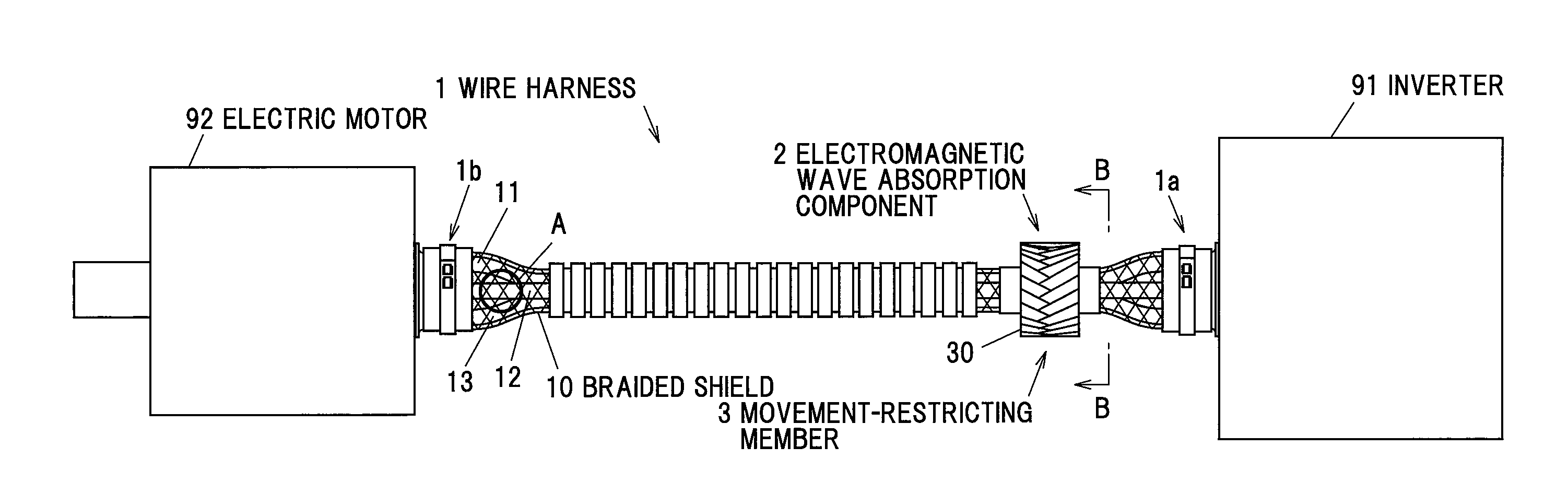
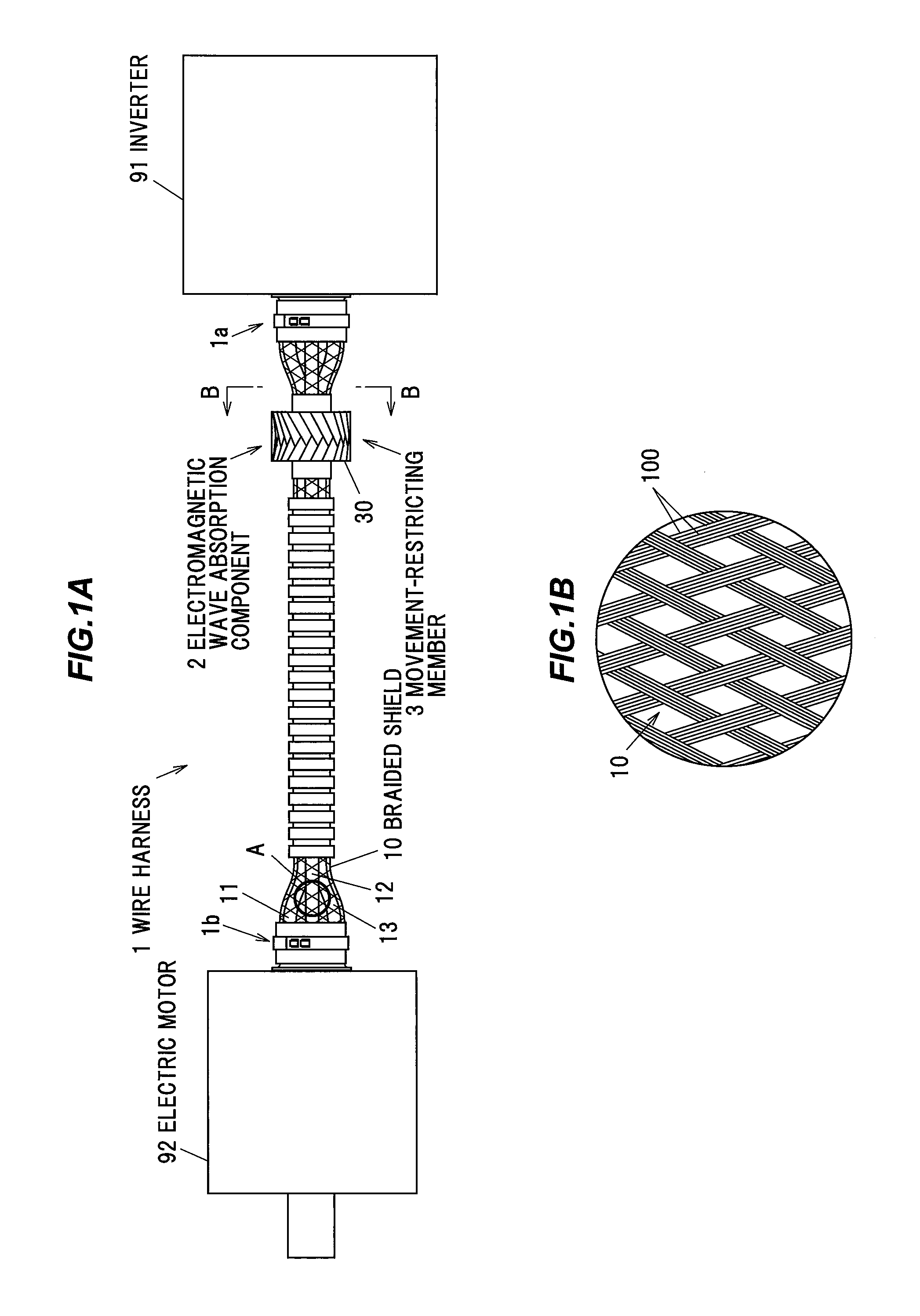
[0024]FIG. 1 shows a wire harness 1 in the embodiment of the invention and also an inverter 91 and an electric motor 92 which are connected by the wire harness 1, wherein FIG. 1A is an overall view and FIG. 1B is an enlarged view of a section A in FIG. 1A.
[0025]The wire harness 1 is installed in, e.g., a vehicle to supply an electric current, which is output from the inverter 91 under PMW (Pulse Width Modulation) control, to the electric motor 92 as a drive source for running the vehicle. The electric current contains harmonic components produced by switching a state of a switching element such as power transistor.
[0026]On the wire harness 1, a first wire holding portion 1a to be fixed to a case of the inverter 91 is provided at one end portion and a second wire holding portion 1b to be fixed to a case of the electric motor 92 is provided at another end portion. In addition, the wire harness 1 is provided with plural (three) electric wires (first to third electric wires 11 to 13) fo...
second embodiment
[0065]Next, the second embodiment of the invention will be described in reference to FIG. 7. FIG. 7 is a cross sectional view showing a wire harness 1A in the periphery of the electromagnetic wave absorption component 2 and the movement-restricting member 3 in the second embodiment. In FIG. 7, constituent elements having the same functions as those described in the first embodiment are denoted by the same reference numerals and the overlapping explanation thereof will be omitted.
[0066]The first to third electric wires 11 to 13 and the electromagnetic wave absorption component 2 are covered with the braided shield 10 and the movement-restricting member 3 is arranged around the braided shield 10 in the wire harness 1A of the second embodiment, while the first to third electric wires 11 to 13 and the braided shield 10 are inserted through the through-hole 20 of the electromagnetic wave absorption component 2 in the wire harness 1 of the first embodiment.
[0067]In the second embodiment, ...
third embodiment
[0070]Next, the third embodiment of the invention will be described in reference to FIG. 8. FIG. 8 is a cross sectional view showing a wire harness 1B in the periphery of the electromagnetic wave absorption component 2 and the movement-restricting member 3 in the third embodiment. In FIG. 8, constituent elements having the same functions as those described in the first embodiment are denoted by the same reference numerals and the overlapping explanation thereof will be omitted.
[0071]In the wire harness 1B of the third embodiment, the movement-restricting member 3 is arranged around the first to third electric wires 11 to 13 and the electromagnetic wave absorption component 2 and the braided shield 10 is further arranged around the movement-restricting member 3.
[0072]In the third embodiment, the resin tape 30 of the movement-restricting member 3 in the first region 31 and the fifth region 35 is wound around and in contact with portions of the first to third electric wires 11 to 13 ex...
PUM
 Abstract
Description
Claims
Application Information