Eureka AIR delivers breakthrough ideas for toughest innovation challenges, trusted by R&D personnel around the world.

Methods and apparatus for broadband frequency comb stabilization

a technology of broadband frequency comb and apparatus, which is applied in the direction of wave amplification devices, electrical devices, laser details, etc., can solve the problem of the shifting device not to shift the second puls

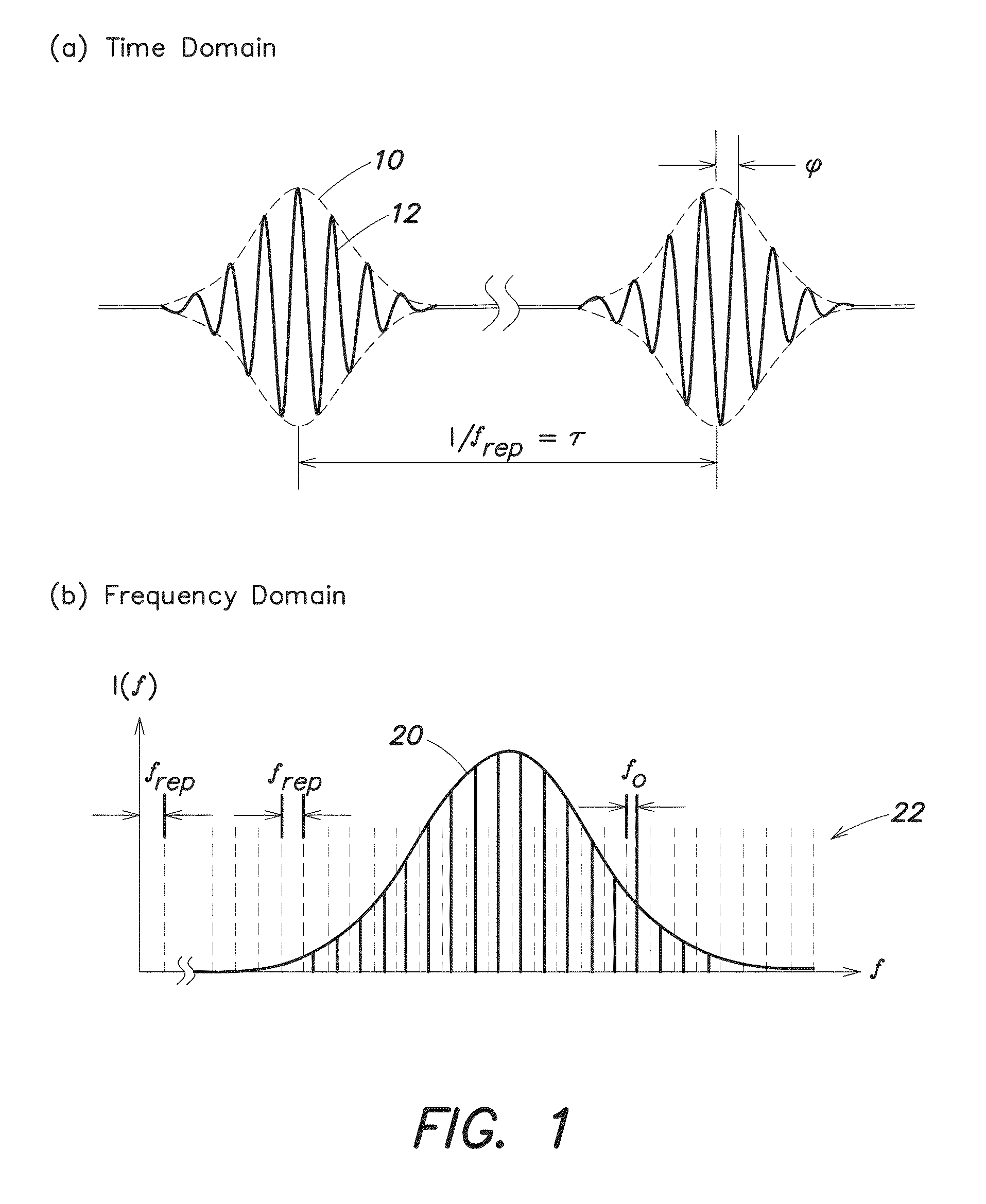
Active Publication Date: 2014-07-03
MASSACHUSETTS INST OF TECH
View PDF6 Cites 38 Cited by
  • Summary
  • Abstract
  • Description
  • Claims
  • Application Information

AI Technical Summary

Benefits of technology

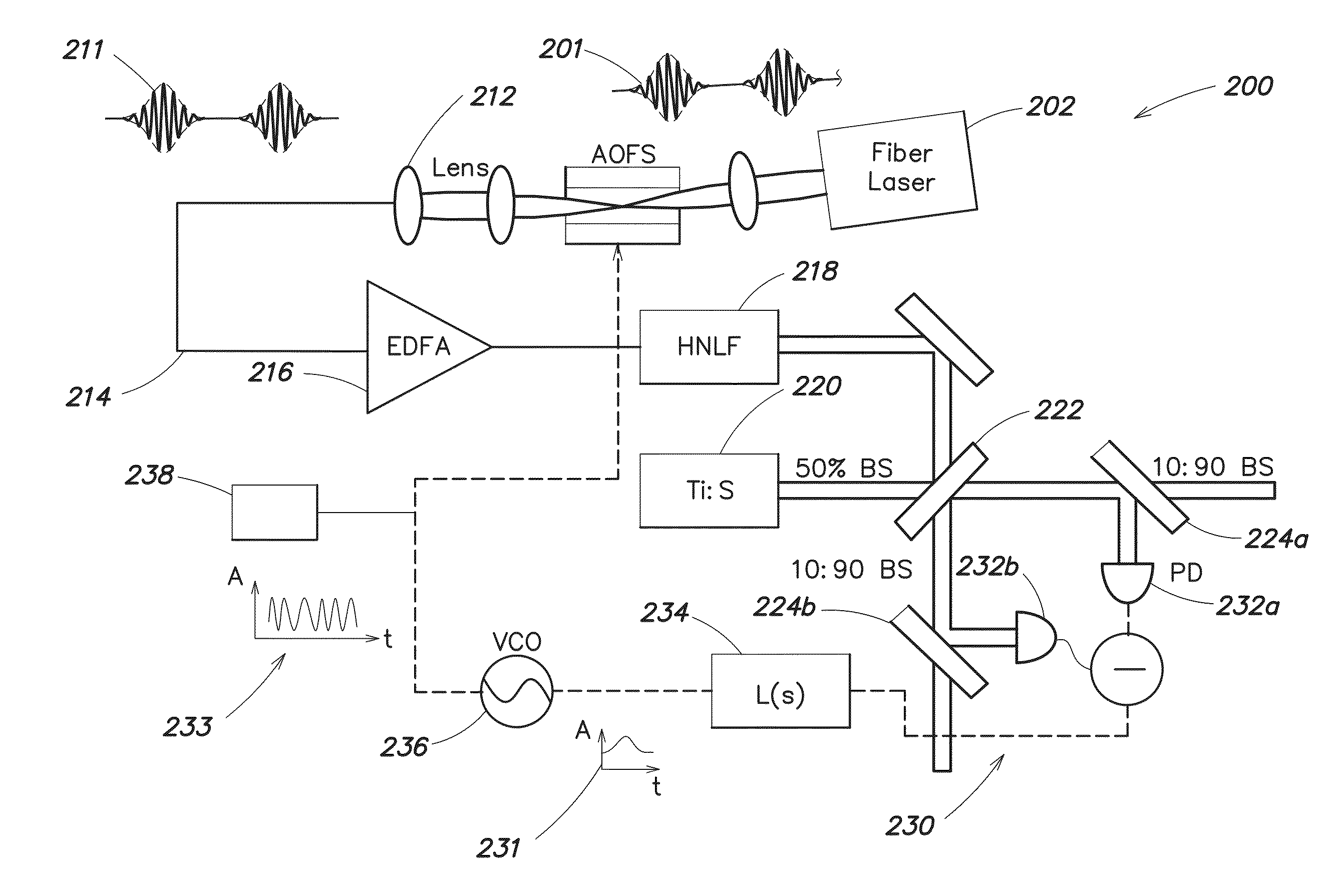
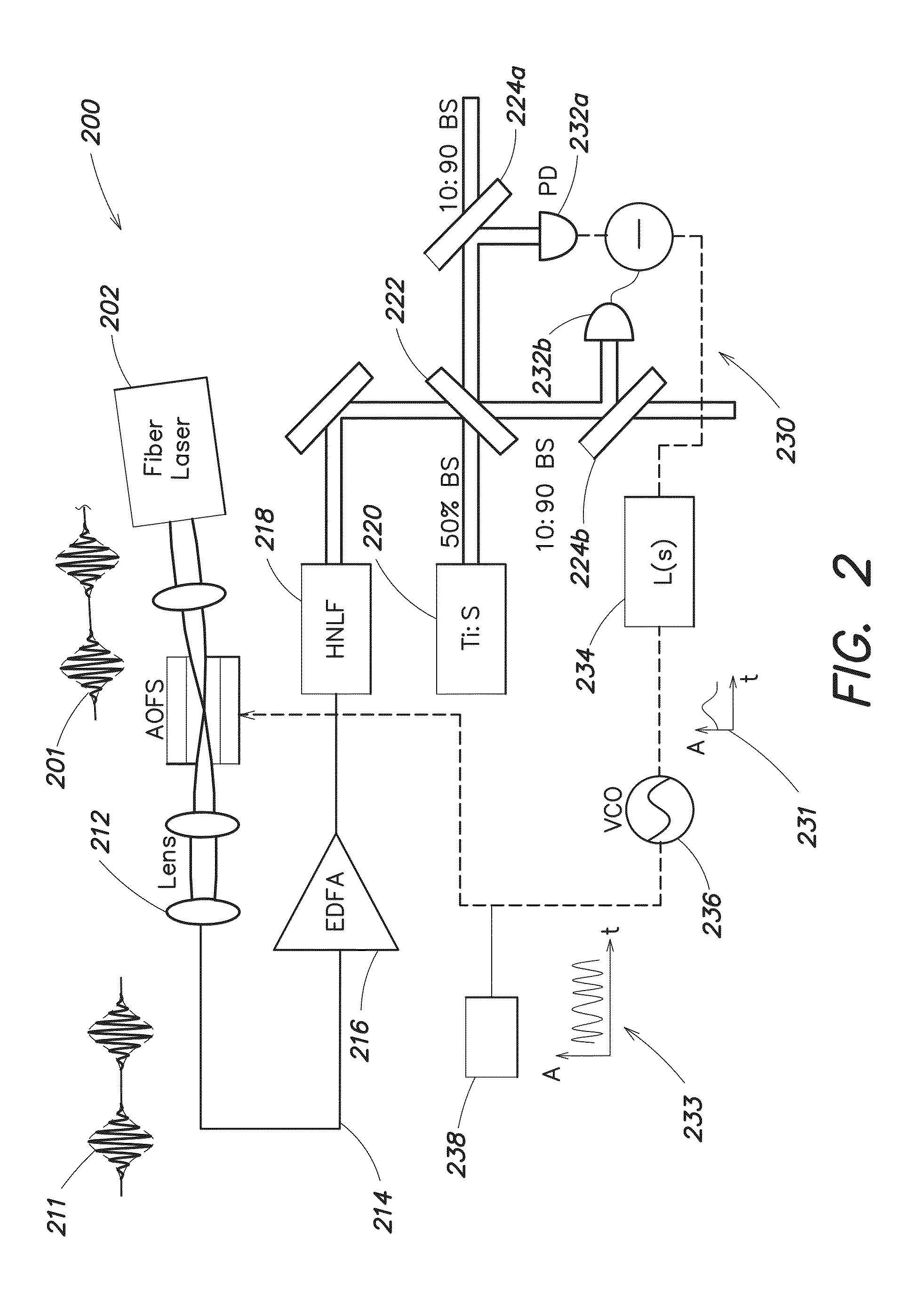
The present invention relates to systems and methods for generating shifted frequency combs. These combs can be used in various applications such as optical communication systems, where they can help to stabilize the carrier-envelope phase of optical signals. The invention includes a frequency comb generator, a frequency-shifting device, and a detector that senses a phase difference between the comb and a reference signal. The detector can provide an error signal that is proportional to the phase difference. The system can also include a controller to shift the first and second pulses of the comb to compensate for changes in the carrier-envelope phase. The invention also includes a reference-signal generator to produce a reference signal, and a detector that senses the phase difference between the comb and the reference signal. Overall, the invention provides a way to generate stable frequency combs with a desired carrier-envelope phase.

Problems solved by technology

For example, the controller may cause the frequency-shifting device to shift the first pulses by an amount sufficient to stabilize the carrier-envelope phase of the first pulses, and it may cause the frequency-shifting device not to shift the second pulses at all.

Method used


Image

  • Methods and apparatus for broadband frequency comb stabilization
  • Methods and apparatus for broadband frequency comb stabilization
  • Methods and apparatus for broadband frequency comb stabilization

Examples


Embodiment Construction

[0022]Following below are more detailed descriptions of various concepts related to, and embodiments of, inventive systems, methods and apparatus for stabilizing broadband frequency combs, synthesizing stabilized broadband frequency combs, and coherently combining stabilized broadband frequency combs. It should be appreciated that various concepts introduced above and discussed in greater detail below may be implemented in any of numerous ways, as the disclosed concepts are not limited to any particular manner of implementation. Examples of specific implementations and applications are provided primarily for illustrative purposes.

[0023]Exemplary techniques for carrier-envelope phase (CEP) stabilization involve implementing feedback using a frequency-shifting device, such as an acousto-optic frequency shifter (AOFS) or a single-sideband (SSB) electro-optic modulator, in a fiber-based, octave-spanning supercontinuum source. In one example, the frequency-shifting device is positioned i...


PUM


Abstract

Feedback loops can be used to shift and stabilize the carrier-envelope phase of a frequency comb from a mode-locked fibers laser or other optical source. Compared to other frequency shifting and stabilization techniques, feedback-based techniques provide a wideband closed-loop servo bandwidth without optical filtering, beam pointing errors, or group velocity dispersion. It also enables phase locking to a stable reference, such as a Ti:Sapphire laser, continuous-wave microwave or optical source, or self-referencing interferometer, e.g., to within 200 mrad rms from DC to 5 MHz. In addition, stabilized frequency combs can be coherently combined with other stable signals, including other stabilized frequency combs, to synthesize optical pulse trains with pulse durations of as little as a single optical cycle. Such a coherent combination can be achieved via orthogonal control, using balanced optical cross-correlation for timing stabilization and balanced homodyne detection for phase stabilization.

Description

CROSS-REFERENCES TO RELATED APPLICATIONS[0001]This application is a bypass continuation application of International Patent Application No. PCT / US2012 / 055096, which was filed on Sep. 13, 2012, and which claims the benefit, under 35 U.S.C. §119(e), of U.S. Provisional Patent Application No. 61 / 534,511, filed on Sep. 14, 2011, under Atty. Docket No. MIT 15107K, entitled “Broadband Frequency Comb Synthesis of Diffraction Limited, Ultrafast Pulse Train with an Acousto-Optic Frequency Shifter in Feedback Configuration,” which applications are hereby incorporated herein by reference in their respective entireties.GOVERNMENT SUPPORT[0002]This invention was supported, in whole or in part, by Department of Energy grant DE-SC0005262 and Air Force Office of Scientific Research grant FA9550-10-1-0063. The Government has certain rights in this invention.BACKGROUND[0003]Frequency combs based on ultrafast lasers and other frequency comb sources are immensely powerful tools for a wide range of appl...

Claims


Application Information

Patent Timeline
IPC IPC(8): H01S3/13
CPCH01S3/1304H01S3/1307H01S3/2391H01S3/0057H01S3/0085H01S3/0092H01S3/1305
Inventor COX, JONATHAN A.KAERTNER, FRANZ X.
Owner MASSACHUSETTS INST OF TECH
Why Eureka
Eureka Blog
Learn More