Ct apparatus without gantry

a gantry and apparatus technology, applied in the field of gantry-less ct apparatuses, can solve the problems of large volume, complicated structure of the apparatus, and loud operation noise, and achieve the effect of reducing the floor space, improving the availability of the gantry-less ct system, and overcompensating the disadvantages of complicated structure and bulky volum

Active Publication Date: 2014-07-03
NUCTECH CO LTD +1
View PDF6 Cites 5 Cited by
  • Summary
  • Abstract
  • Description
  • Claims
  • Application Information

AI Technical Summary

Benefits of technology

[0027]The present invention can adopt a carbon nanotube X-ray source. By laying out the X-ray source and the detector modules reasonably, the present invention overcomes the disadvantages of the complicated structure and bulky volume of the conventional gantry-less CT apparatus, thereby achieving miniaturization of the CT safety inspection apparatus, reducing its floor space, and improving availability of the gantry-less CT system in a safety inspection site.
[0028]The gantry-less CT system based on the carbon nanotube X-ray source according to the present invention can ensure, by controlling emission of the carbon nanotube X-ray source and optimizing layout of a detector arm, that enough data required by the gantry-less CT system are acquired under the conditions of a small width size of the CT apparatus, thereby reducing its floor space and cost.

Problems solved by technology

Since rotary components are used, the apparatus has a complicated structure, loud operational noise, a great volume, and a high operation and maintenance cost.
How to lay out the ray source and detector reasonably also becomes one of the difficulties confronted by gantry-less CT apparatus manufacturers.
Therefore, radiation shield requirements for the apparatus itself are high.

Method used


Image

  • Ct apparatus without gantry
  • Ct apparatus without gantry

Examples


Embodiment Construction

[0032]A further description of the invention will be made as below with reference to embodiments of the present invention taken in conjunction with the accompanying drawings.

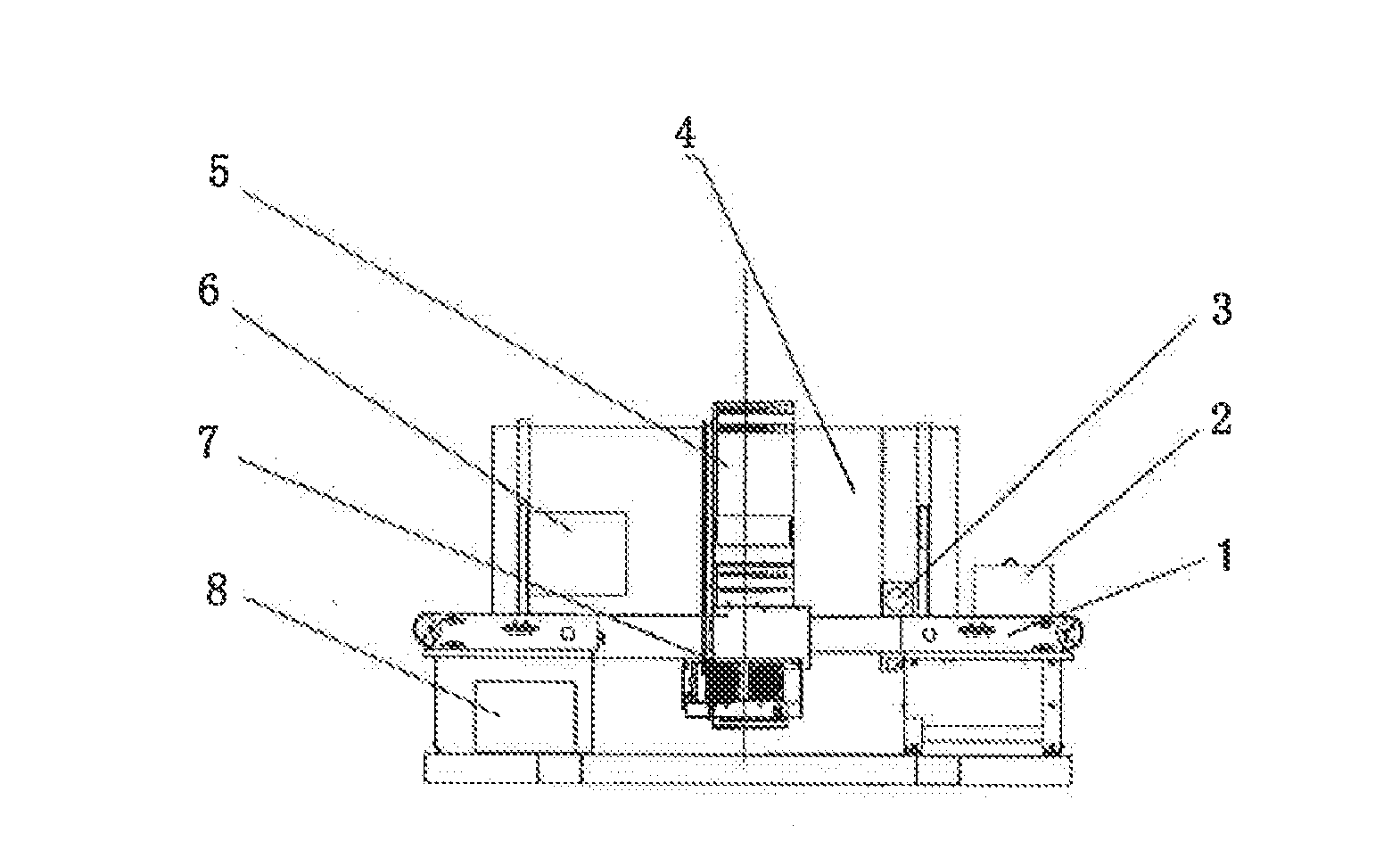
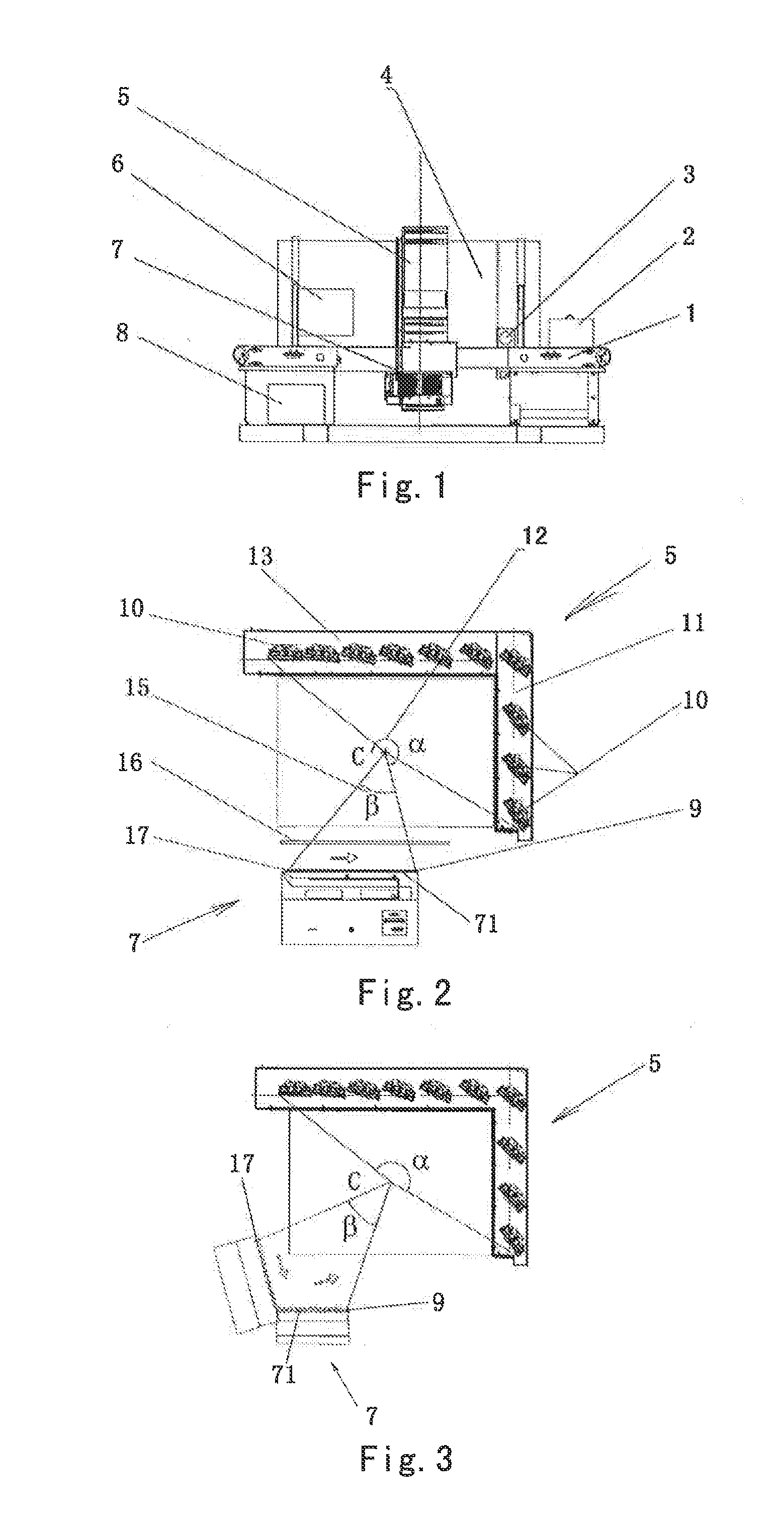
[0033]As shown in FIGS. 1-3, a CT apparatus without a gantry according to an embodiment of the present invention comprises: a scanning passage 4; a stationary X-ray source 7 including a plurality of ray emission focal spots 71; and a plurality of stationary detector modules 10. The detector modules 10 are mounted on the detector arm 5, and the detector arm 5 is disposed opposite the X-ray source 7. Furthermore, the detector modules 10 are arranged in a substantially L shape when viewed in a plane intersecting the scanning passage 4 (the plane may be substantially perpendicular to the scanning passage or the plane may be inclined with respect to the scanning passage), i.e., there are a transverse arm 13 and a vertical arm 11 which are connected to each other without a gap therebetween. A plane in which the ray em...


PUM


Abstract

A CT apparatus without a gantry. The CT apparatus includes a scanning passage; a stationary X-ray source arranged around the scanning passage and including a plurality of ray emission focal spots; and a plurality of stationary detector modules arranged around the scanning passage and disposed opposite the X-ray source. At least some of the plurality of detector modules may be arranged substantially in an L shape, a semicircular shape, a U shape, an arc shape, a parabolic shape, or a curve shape when viewed in a plane intersecting the scanning passage. The invention ensures that the stationary gantry type CT system has a small size, and a high data identification accuracy.

Description

PRIORITY CLAIM[0001]The present application claims priority to Chinese Patent Application No. 201210581712.8 filed on Dec. 27, 2012, which said application is incorporated by reference in its entirety herein.BACKGROUND OF THE INVENTION[0002]1. Field of the Invention[0003]The present invention relates to a CT apparatus without a gantry, and in particular to a CT apparatus, without a gantry, for safety inspection.[0004]2. Description of the Related Art[0005]Application of CT technology to a safety inspection system is increasingly developed due to the superexcellent performance of CT technology in identification of substance density. However, since CT technology requires that data are acquired at different angles for data reconstruction, conventional X-ray radioscopy data are acquired at different angles by a gantry system rotating at a speed for reconstruction. Since rotary components are used, the apparatus has a complicated structure, loud operational noise, a great volume, and a h...

Claims


Application Information

Patent Timeline
Patent Type & Authority Applications(United States)
IPC IPC(8): G01V5/00
CPCG01T1/2985G01N2223/419G01N23/046G01V5/005G01V5/0041A61B6/035A61B6/4429
Inventor ZHANG, JINYUTANG, HUDUAN, ZHANJUNZHANG, LIZHAO, ZIRAN
Owner NUCTECH CO LTD
Why Eureka
Try Eureka