
Operating machine

a working machine and battery technology, applied in machines/engines, positive displacement liquid engines, pump parameters, etc., can solve the problems of deteriorating capability of the working machine, operator's strangeness on an operation, and engine cannot bear a load solely, so as to achieve excellent operation performance and maintain high operability.

Active Publication Date: 2014-07-03
NIHON KENKI CO LTD
View PDF5 Cites 2 Cited by
  • Summary
  • Abstract
  • Description
  • Claims
  • Application Information

AI Technical Summary

Benefits of technology

The invention is a type of working machine that can use either cables or batteries for power. It has a feature that lets you set a specific amount of electricity to be stored in its battery, and determine how long it can operate based on that amount of stored electricity. It also has a function that lets you know if it can make it to the end of the set operation time based on its current battery level. When it can't, the machine automatically reduces the amount of electricity it can use, which improves its performance and keeps it running efficiently. This design ensures a long battery life and excellent performance during operation.

Problems solved by technology

However, when the mode is suddenly changed over to a mode in which the hydraulic pump is driven only by the engine in the stage where the amount of electricity stored in the electric storage device has reached the lower limit value, the engine cannot bear a load solely but may fall into engine stall.
Therefore, there is another problem that a feeling of strangeness on an operation may be given to an operator.
Further, when the amount of electricity stored in the electric storage device reaches the lower limit value in the middle of a preset operation scheduled time of one day, the capability of the working machine deteriorates since then.
Therefore, there arises another problem that a scheduled operation cannot be completed.

Method used


Image

  • Operating machine
  • Operating machine
  • Operating machine

Examples


example 1

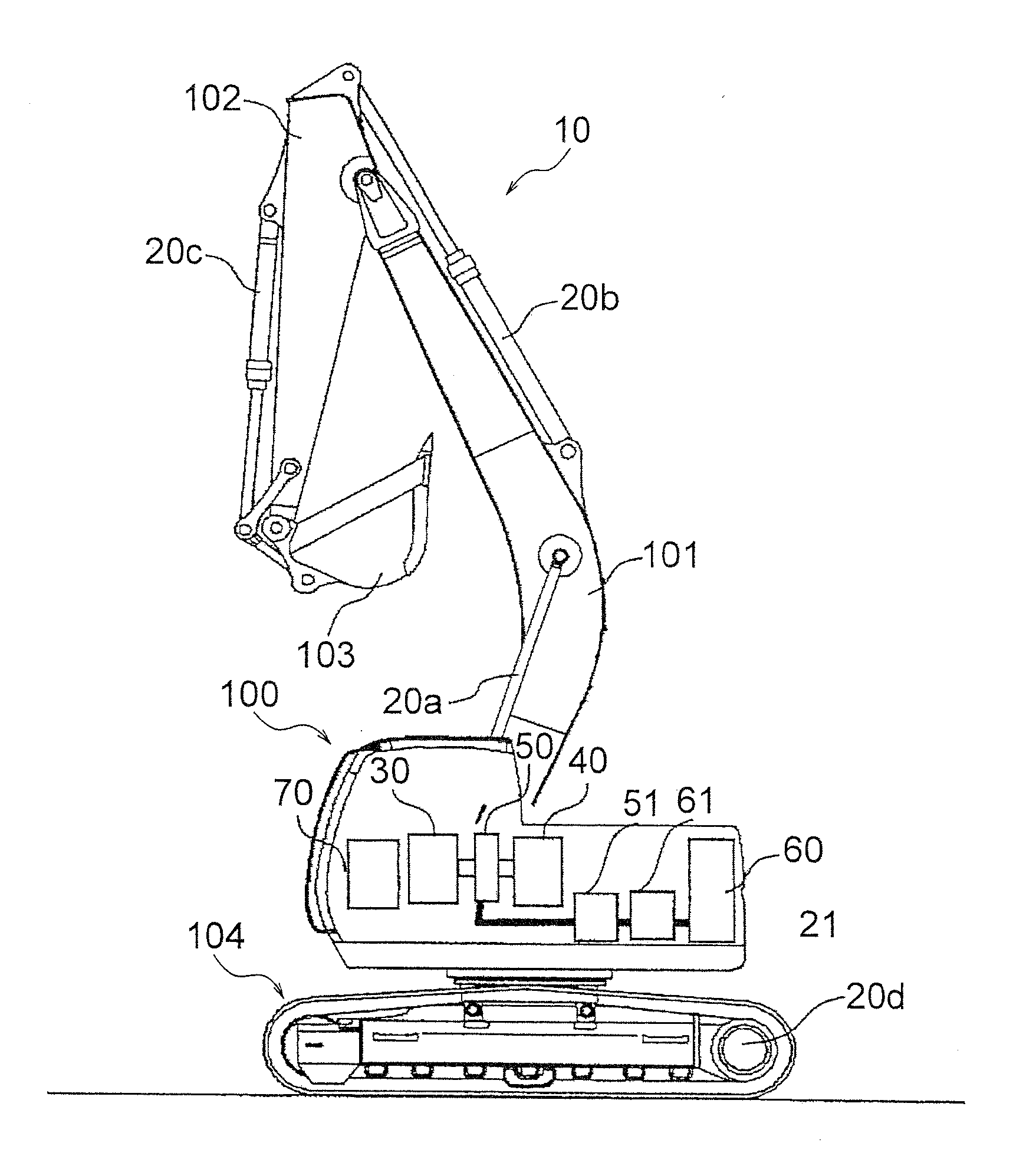
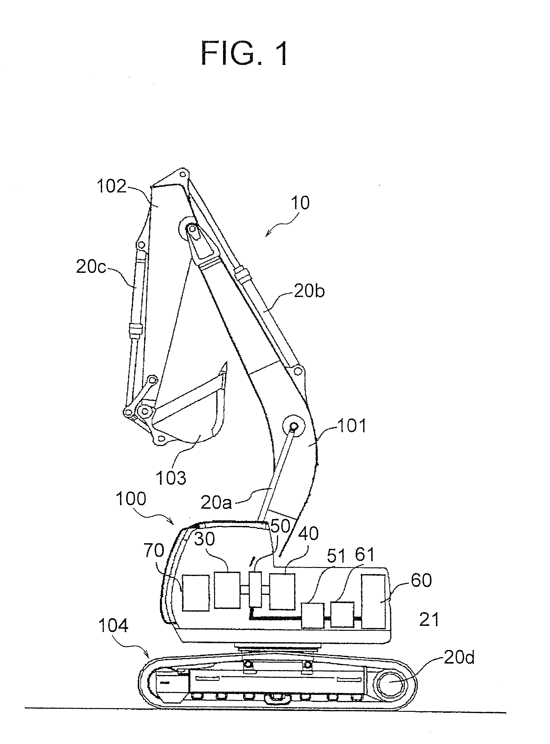
[0033]A plug-in hybrid type hydraulic excavator 10 shown in FIG. 1 has a boom 101, an arm 102, a bucket 103, a crawler 104 and a revolving structure 100 as operating portions. The boom 101, the arm 102 and the bucket 103 are driven by hydraulic cylinders 20a, 20b and 20c which are hydraulic actuators, respectively. On the other hand, the crawler 104 for travelling is driven by a hydraulic motor 20d which is a hydraulic actuator, and the revolving structure 100 is also driven by a not-shown hydraulic motor which is a hydraulic actuator. These hydraulic actuators 20a to 20d are driven by pressure oil ejected from a hydraulic pump 30. The hydraulic pump 30 is a variable displacement hydraulic pump. The displacement (the amount of pressure oil ejected by one revolution) of the hydraulic pump 30 can be changed when the tilt angle thereof is changed. The drive shaft of the hydraulic pump 30 is connected coaxially with an engine 40 and an electric motor 50. The hydraulic pump 30 is operate...

example 2

[0047]Next, Example 2 of the working machine according to the invention will be described with reference to FIG. 7. According to this example, as shown in FIG. 7, the difference between the new pump absorption horsepower maximum value and the old pump absorption horsepower maximum value is divided into a region A whose target flow rate Q is high, a region B whose target flow rate Q is medium and a region C whose target flow rate Q is low. When the pump absorption horsepower maximum value is reduced, the part corresponding to the region A of the old pump absorption horsepower maximum value is first reduced to the new pump absorption horsepower maximum value, the part corresponding to the region B of the old pump absorption horsepower maximum value is next reduced to the new pump absorption horsepower maximum value, and the part corresponding to the region C of the old pump absorption horsepower maximum value is finally reduced to the new pump absorption horsepower maximum value. In t...


PUM


Abstract

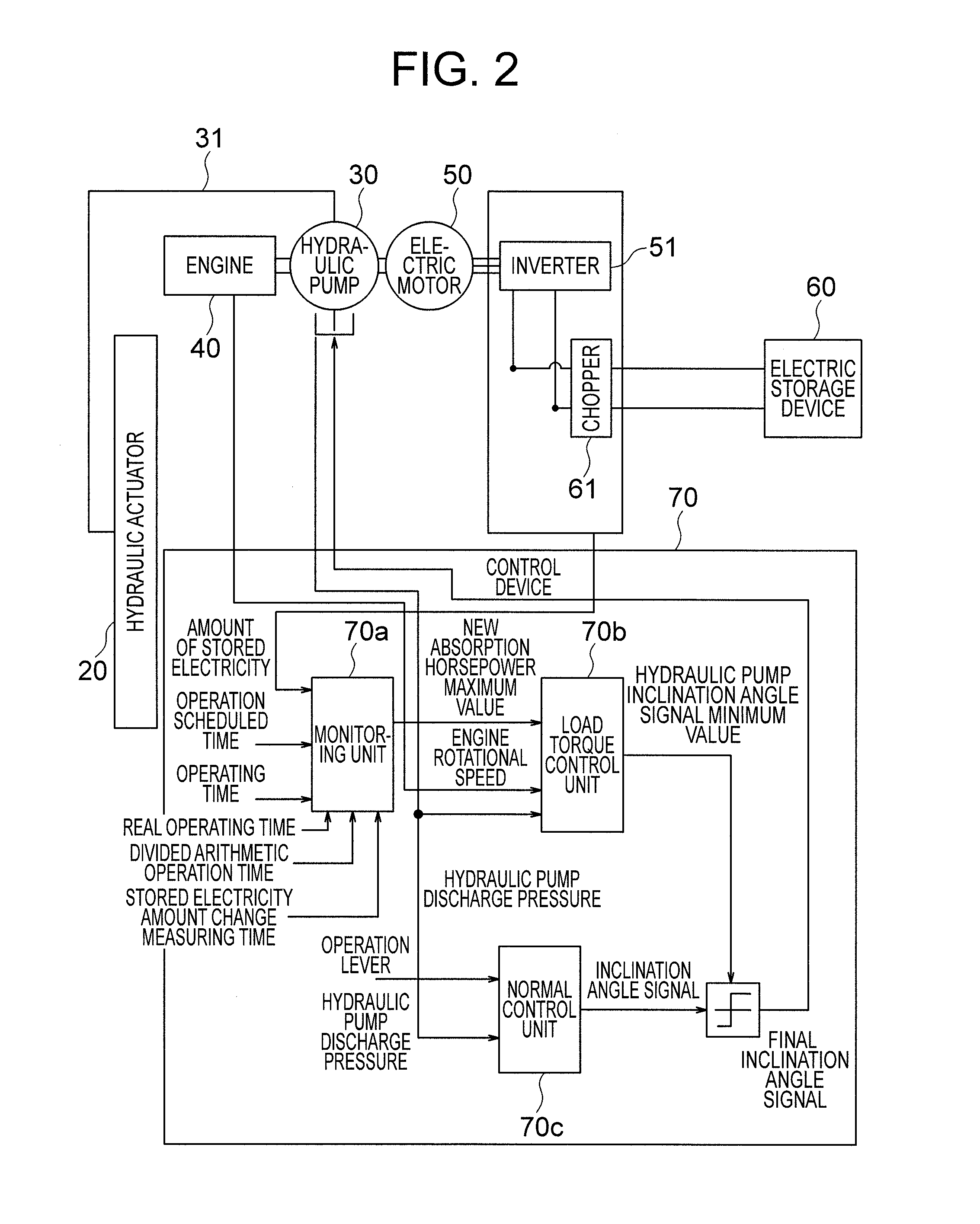
To provide a hybrid type or battery type working machine which hardly gives a feeling of strangeness on an operation to an operator and in which electric power stored in a storage battery can be used effectively within an operation scheduled time set in advance.An amount of reduction in the amount of electricity stored in an electric storage device 60 in a predetermined time t1 after an working machine starts up is obtained, and an operation possible time t2 is obtained from the obtained amount of reduction and a residual amount of the electricity stored in the electric storage device 60. Further, determination is made as to whether the obtained operation possible time t2 reaches a remaining time of an operation scheduled time obtained by subtracting a currently spent real operation time from the operation schedule time set in advance. When determination is made that the operation possible time t2 does not reach the remaining time of the operation schedule time, a pump absorption horsepower maximum value is reduced to such a value that the operation possible time can reach the remaining time of the operation scheduled time.

Description

TECHNICAL FIELD[0001]The present invention relates to a hybrid type or battery type working machine provided with an electric motor which is driven for power running by electric power supplied from an electric storage device so as to serve as a drive source for a hydraulic pump. Particularly, it relates to a method for effectively using electric power stored in the electric storage device.BACKGROUND ART[0002]A hybrid type working machine has a configuration in which a hydraulic pump is driven by an engine and an electric motor (a motor generator is generally used, and the “electric motor” mentioned in this specification includes the motor generator.) driven for power running by electric power stored in an electric storage device, and hydraulic actuators are driven by pressure oil ejected from the hydraulic pump so as to perform a required operation. Assume that when the hybrid type working machine is in operation, the amount of electricity stored in the electric storage device reach...

Claims


Application Information

Patent Timeline
Patent Type & Authority Applications(United States)
IPC IPC(8): F04B49/06
CPCF04B49/065E02F9/207E02F9/2075E02F9/2091E02F9/2235B60L1/003B60L2200/40B60L2240/80H02J7/00716H02J7/04E02F9/20F04B49/103F04B49/20F04B49/10F04B2201/1203F04B1/26F04B27/14Y02T10/70
Inventor SASAKI, MASATAKASATAKE, HIDETOSHI
Owner NIHON KENKI CO LTD
Learn More