Ion Guide Coupled to MALDI Ion Source

a technology of ion guide and maldi ion source, which is applied in the direction of particle separator tube details, dispersed particle separation, separation process, etc., can solve the problems of reducing instrument yield, affecting the accuracy of ion guide, so as to improve the efficiency of matrix imaging and/or profiling, improve the rate of acquisition, and improve the effect of ion imaging and/or depth profiling applications

Active Publication Date: 2014-07-10
MICROMASS UK LTD
View PDF1 Cites 35 Cited by
  • Summary
  • Abstract
  • Description
  • Claims
  • Application Information

AI Technical Summary

Benefits of technology

[0124]Advantageously, the preferred embodiment enables significant improvements in ion imaging and / or depth profiling applications since the preferred embodiment enables the integrity of each discrete ion packet to be maintained whilst allowing ions from multiple laser shots to be rapidly and simultaneously transmitted through the mass spectrometer whilst keeping the packets of ions segregated from each other thereby resulting in a significant increase in the rate of acquisition.

Problems solved by technology

The pulse of laser energy results in rapid heating of the region that is irradiated.
Laser Desorption Ionisation relies upon the removal of ions from the surface of a sample and hence is, by its nature, a destructive technique.
However, the production of mass spectra relating to each of the different areas within a tissue sample requires discrete analyses which is time consuming and reduces instrument yield.

Method used


Image

  • Ion Guide Coupled to MALDI Ion Source
  • Ion Guide Coupled to MALDI Ion Source
  • Ion Guide Coupled to MALDI Ion Source

Examples


Embodiment Construction

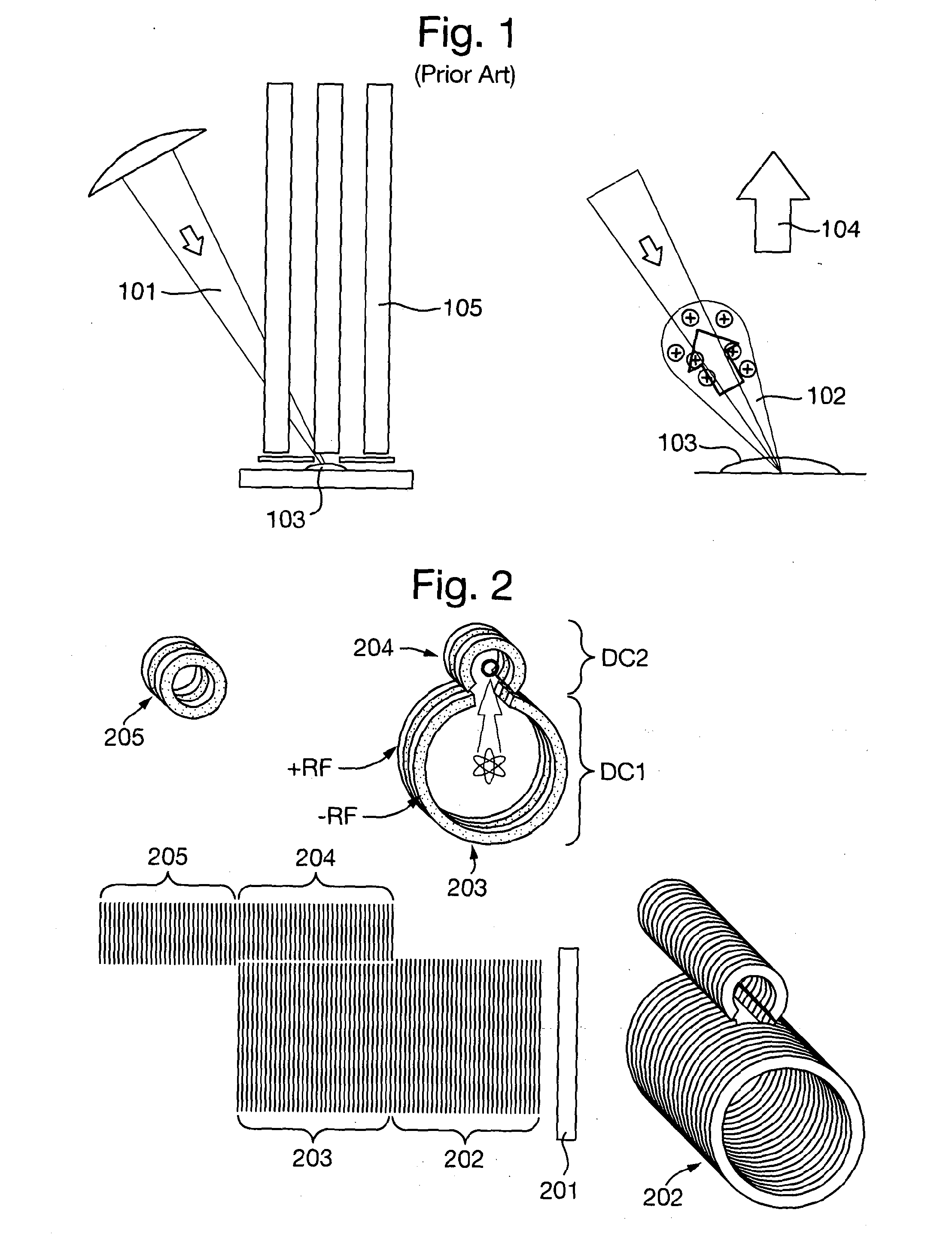
[0218]A known arrangement will first be described. FIG. 1 shows a MALDI sample urinated by a laser beam 101. The angle of incidence of the laser beam 101 determines the dominant direction of emission of the resulting plume of material 102.

[0219]An RF ion guide 105 is shown adjacent the sample plate. The on guide 105 is arranged to have a direction of acceleration 104 and an axis of confinement 105 as shown. The RF on guide 105 is shown located adjacent a sample 103 as is the case for a typical MALDI mass spectrometer.

[0220]The plume 102 and the analyte ions therein which are formed subsequent to irradiation by the laser beam 101 tend to expand in a direction towards the incident laser beam 101. This is because of the inhomogeneous surface topography of the MALDI sample and crystalline matrix. Reference is made, for example, to P. Aksouh et al. Rapid Commun. Mass Spectrometry, 9 (1995) 515.

[0221]The ions formed in the MALDI plume 102 must be transferred into the analyser.

[0222]This r...


PUM


Abstract

A pulsed ion source is disclosed wherein the ion source is energised one or more times to generate a first group of ions and a second group of ions. The first and second groups of ions are simultaneously transmitted through an ion guide whilst keeping the first and second groups of ions isolated from each other.

Description

CROSS-REFERENCE TO RELATED APPLICATION[0001]This application claims priority from and the benefit of U.S. Provisional Patent Application Ser. No. 61 / 508,285 filed on 15 Jul. 2011 and United Kingdom Patent Application No. 1111568.0 filed on 6 Jul. 2011. The entire contents of these applications are incorporated herein by reference.[0002]The present invention relates to a method of mass spectrometry and a mass spectrometer.BACKGROUND TO THE PRESENT INVENTION[0003]Mass spectrometers configured for Matrix Assisted Laser Desorption Ionisation (“MALDI”) are known. MALDI is a soft ionisation technique for mass spectrometry in which analyte molecules are prepared on the surface of a target plate. The analyte molecules are supported in a solid polycrystalline matrix. A pulse of laser radiation, with a typical duration of a few nanoseconds, is directed onto the MALDI sample. The laser radiation is strongly absorbed by the matrix molecules.[0004]The pulse of laser energy results in rapid heati...

Claims


Application Information

Patent Timeline
Patent Type & Authority Applications(United States)
IPC IPC(8): H01J49/10H01J49/00
CPCH01J49/0031H01J49/10H01J49/061H01J49/065H01J49/161H01J49/04H01J49/164
Inventor WILDGOOSE, JASON LEEPRINGLE, STEVEN DEREKGILES, KEVILBROWN, JEFFERY MARKMURRAY, PAULKENNY, DANIEL JAMES
Owner MICROMASS UK LTD
Why Eureka
Try Eureka