Electric machine with multiple air gaps and a 3D magnetic flux

a technology of electric machines and air gaps, applied in the field of electric machines, can solve the problems of reducing the performance of current electric motors, unsuitable for high rotation speed, and inconvenient use of electrical contacts between, so as to improve the use of magnetic fields, enhance the performance of such electric machines, and improve the power-to-weight ratio

Active Publication Date: 2014-07-10
EUROCOPTER +2
View PDF5 Cites 37 Cited by
  • Summary
  • Abstract
  • Description
  • Claims
  • Application Information

AI Technical Summary

Benefits of technology

[0046]Thus, the goal of the present invention is to offer an electric machine that makes it possible to overcome the above-mentioned limitations, in order to improve the use of the magnetic field that is generated in the vicinity of the stator, thereby enhancing the performance of such an electric machine, including, in particular, its power-to-weight ratio, thanks to the presence of at least two air gaps and the circulation of a magnetic flux in three dimensions.

Problems solved by technology

A principal disadvantage of such a direct-current electric motor resides in the electrical contacts that are necessary between the rotor coil and the rotating collector.
These contacts, which are obtained for example by means of brushes, can create electric arcs that in particular cause wear, and parasitic currents that consequently require frequent maintenance schedules for the electric machine.
Furthermore, this type of electric motor is not suitable for high rotation speeds, and consumes energy due to friction, thereby reducing its performance.
Finally, it can be complex to implement.
However, the use of these electric machines today is limited by certain constraints, such as the power-to-weight ratio of the machines and of the electric-energy storage means.
Furthermore, the power-to-weight ratio of these electric machines—namely, the ratio of their power to their mass—and their manufacturing cost will vary depending on the magnetic-flux configurations that are used, without necessarily being optimal.
However, the power-to-weight ratio is not optimal, because these electric machines use only one orientation of the magnetic flux created from the magnetic field generated by the stator operating in motor mode.
Thus, using this technology, in order to have high torque machines it would be necessary to increase either the radius (for radial machines) or the length (for axial machines) of the air gap, which would result in large and heavy machines.
Thus, this technology does not use all of the possibilities for the orientation of the magnetic flux, and does not allow the creation of high torque electric machines that are also compact and light.
In fact, such a tooth shape allows the magnetic flux to circulate maximally in the magnetic circuit, which consists, among other things, of the stator yoke, thereby limiting both its circulation in air and magnetic leakage.

Method used


Image

  • Electric machine with multiple air gaps and a 3D magnetic flux
  • Electric machine with multiple air gaps and a 3D magnetic flux
  • Electric machine with multiple air gaps and a 3D magnetic flux

Examples


first embodiment

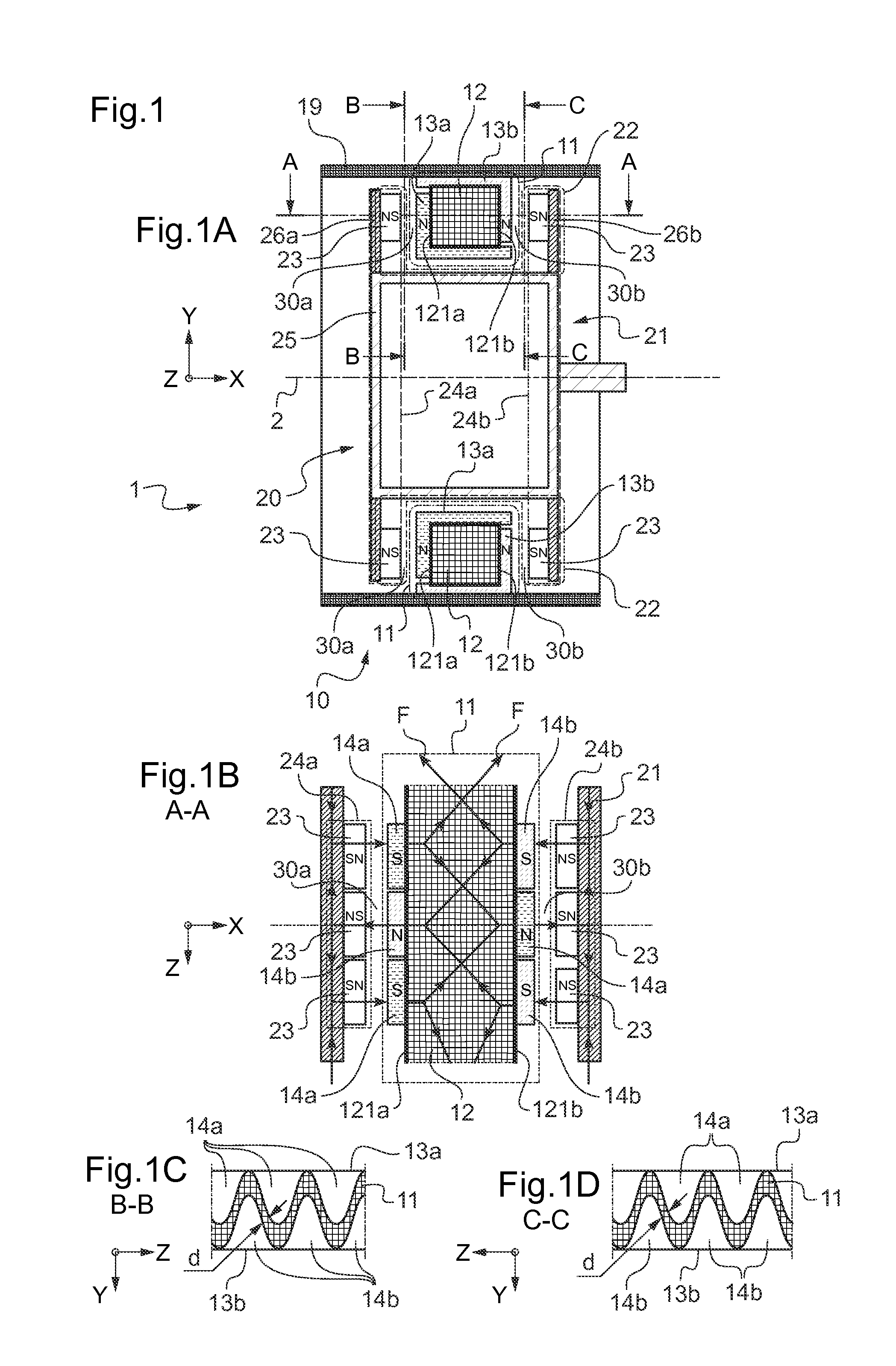
[0140]FIG. 1 shows an electric machine 1 that relates to the invention. According to FIG. 1A, such an electric machine 1 includes an axis of rotation 2, a stator 10 and a rotor 20 that revolves about the axis of rotation 2 and inside the stator 10.

[0141]The rotor 20 includes a structure 21 and an annular receiver unit 22 that is provided with two rows 24a, 24b of magnets 23, each magnet 23 having a first north pole and a first south pole. Each row 24a, 24b thereby consists of alternating first north poles and first south poles.

[0142]This structure 21 of the rotor 20 consists of two first parts 26a, 26b on which the two rows 24a, 24b of magnets 23 are respectively positioned, and a second part 25 that notably allows the fastening of these two first parts 26a, 26b.

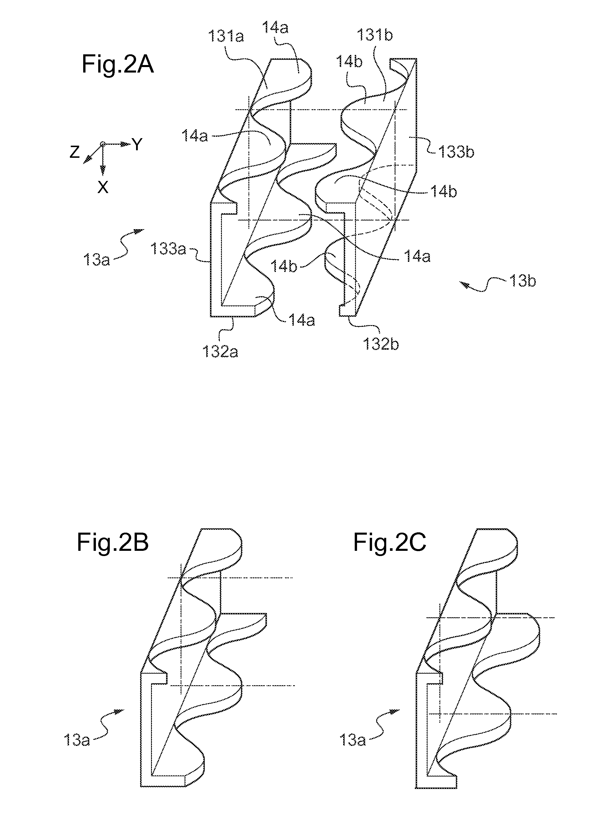
[0143]The stator 10 consists of an armature 19 and an annular exciter unit 11 that is equipped with a coil 12 and two identical annular yokes 13a, 13b. One portion of these yokes 13 is shown in FIG. 2A. Each yoke 13 consist...

second embodiment

[0205]FIG. 13 shows a variant of the invention, which includes, in the same way as before, an axis of rotation 2, a stator 10, and a rotor 20 rotating about the axis of rotation 2 and outside the stator 10.

[0206]The rotor 20 includes a structure 21 and an annular receiver unit 22 equipped with three rows of magnets 23, and the stator 10 includes an armature 19 and an annular exciter unit 11 equipped with a coil 12 and three annular yokes 13a, 13b, 13c. According to this variant, the rotor 20 rotates about the axis of rotation 2 outside the stator and outside the exciter unit 11. This structure 21 of this rotor 20 includes three first parts 26a, 26b, 26c, upon which are positioned, respectively, the three rows of magnets 23, and a second part 25a, 25b that allows these three first parts 26a, 26b, 26c to be attached, while ensuring magnetic isolation between them.

[0207]Each yoke 13a, 13b, 13c includes a plurality of teeth that are distributed angularly, in a regular manner, on each ex...

third embodiment

[0216]FIG. 18 shows an electric machine 1 that relates to the invention. According to FIG. 18A, such an electric machine 1 includes an axis of rotation 2, a stator 10 and a rotor 20 that revolves about the axis of rotation 2 and inside the stator 10.

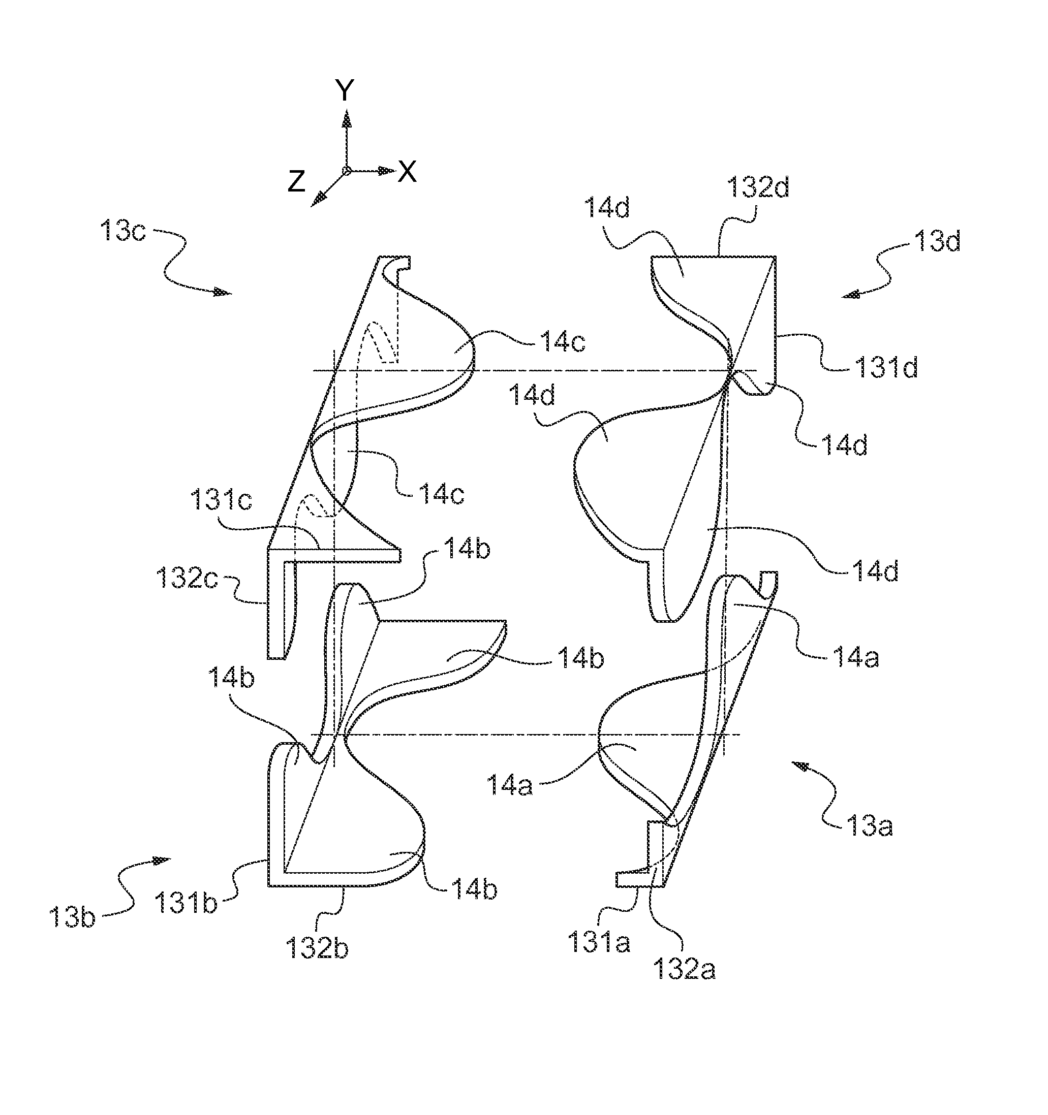
[0217]The rotor 20 includes a structure 21 and an annular receiver unit 22 equipped with four rows 24a, 24b, 24c, 24d of magnets 23, with each magnet 23 having a first north pole and a first south pole. Each row 24a, 24b, 24c, 24d thereby consists of alternating first north poles and first south poles. This structure 21 of this rotor 20 includes four first parts 26a, 26b, 26c, 26d upon which are positioned, respectively, the four rows 24a, 24b, 24c, 24d of magnets 23, and a second part 25a, 25, 25c that allows these four first parts 26a, 26b, 26c, 26d to be attached, while ensuring magnetic isolation between them.

[0218]The stator 10 includes an armature 19 and an annular exciter unit 11 equipped with a coil 12 and four annular yokes 13a,...


PUM


Abstract

The present invention relates to an electric machine (1) that includes a stator (10) and a rotor (20), with the said stator (10) being equipped with at least one annular exciter unit (11) that includes a coil (12) and at least two annular yokes (13a, 13b), with the said rotor being equipped with a structure (21) and at least one annular receiver unit (22). Each receiver unit (22) includes at least two rows (24) of magnets (23). Two sides (131, 132) of each yoke (13) include teeth (14) distributed angularly in a regular manner, and the said teeth (14) of the two adjacent yokes (13) fit onto a face (121) of the said exciter unit (11), alternately forming north poles and south poles. Each row (24) of the said magnets (23) is positioned opposite one face (121), forming an air gap (30) with the said exciter unit (11), with the electric machine (1) thus including at least two air gaps (30), with a 3D magnetic flux thus circulating inside the said electric machine (1), dividing and regrouping itself in the vicinity of the said magnets (23) and of the said yokes (13).

Description

CROSS-REFERENCE TO RELATED APPLICATIONS[0001]This application claims priority to French Patent Application No. FR 13 00029 filed Jan. 9, 2013, the disclosure of which is incorporated in its entirety by reference herein.BACKGROUND OF THE INVENTION[0002](1) Filed of the Invention[0003]The present invention lies in the area of electric machines. It relates to a reversible electric machine with multiple air gaps and a 3D magnetic flux. Such an electric machine may be monophase or polyphase.[0004](2) Description of Related Art[0005]An electric machine that converts electrical energy into mechanical energy—for example, for the propulsion of a vehicle—is called a “motor”. An electric machine that converts mechanical energy into electrical energy—for example, for the generation of an electric current—is called a “generator”. Among generators, a distinction can be drawn between alternators, which supply an alternating electric current, and dynamos, which supply a direct electric current.[000...

Claims


Application Information

Patent Timeline
Patent Type & Authority Applications(United States)
IPC IPC(8): H02K1/14
CPCH02K1/145H02K21/24H02K2201/12H02K21/125H02K21/145H02K21/22H02K1/182H02K3/528H02K3/525H02K15/022H02K21/026
Inventor MARIOTTO, DAMIEN
Owner EUROCOPTER
Why Eureka
Try Eureka