Common mode noise filter and production method therefor

a technology of noise filter and production method, which is applied in the direction of coils, transformers/inductance details, inductances, etc., can solve the problems of radiated noise and cracks that can sometimes be produced in the insulating layer between the coil conductors, and achieve excellent high-frequency characteristics and high yield

Active Publication Date: 2014-07-10
PANASONIC INTELLECTUAL PROPERTY MANAGEMENT CO LTD
View PDF4 Cites 33 Cited by
  • Summary
  • Abstract
  • Description
  • Claims
  • Application Information

AI Technical Summary

Benefits of technology

[0014]This common mode noise filter has excellent high-frequency characteristics at a high yield.

Problems solved by technology

This market trend invites a problem of how to deal with radiated noise.
However, the currents of the common mode noise flows in the same direction cause the magnetic fluxes generated in the coils to be combined together and strengthened by each other.
On top of that, even if an appropriate firing condition is found to the simultaneous firing of respective layers of the laminated body, and the laminated body could be formed unitarily, there is still a problem: During a heat-treat step (e.g. baking an external terminal electrode printed on the laminated body) after the firing step, cracks can be sometimes produced in the insulating layers between the coil conductors.

Method used


Image

  • Common mode noise filter and production method therefor
  • Common mode noise filter and production method therefor
  • Common mode noise filter and production method therefor

Examples


exemplary embodiment 1

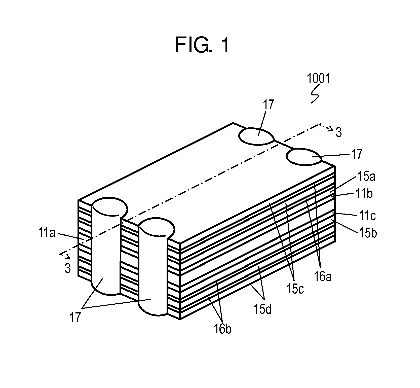
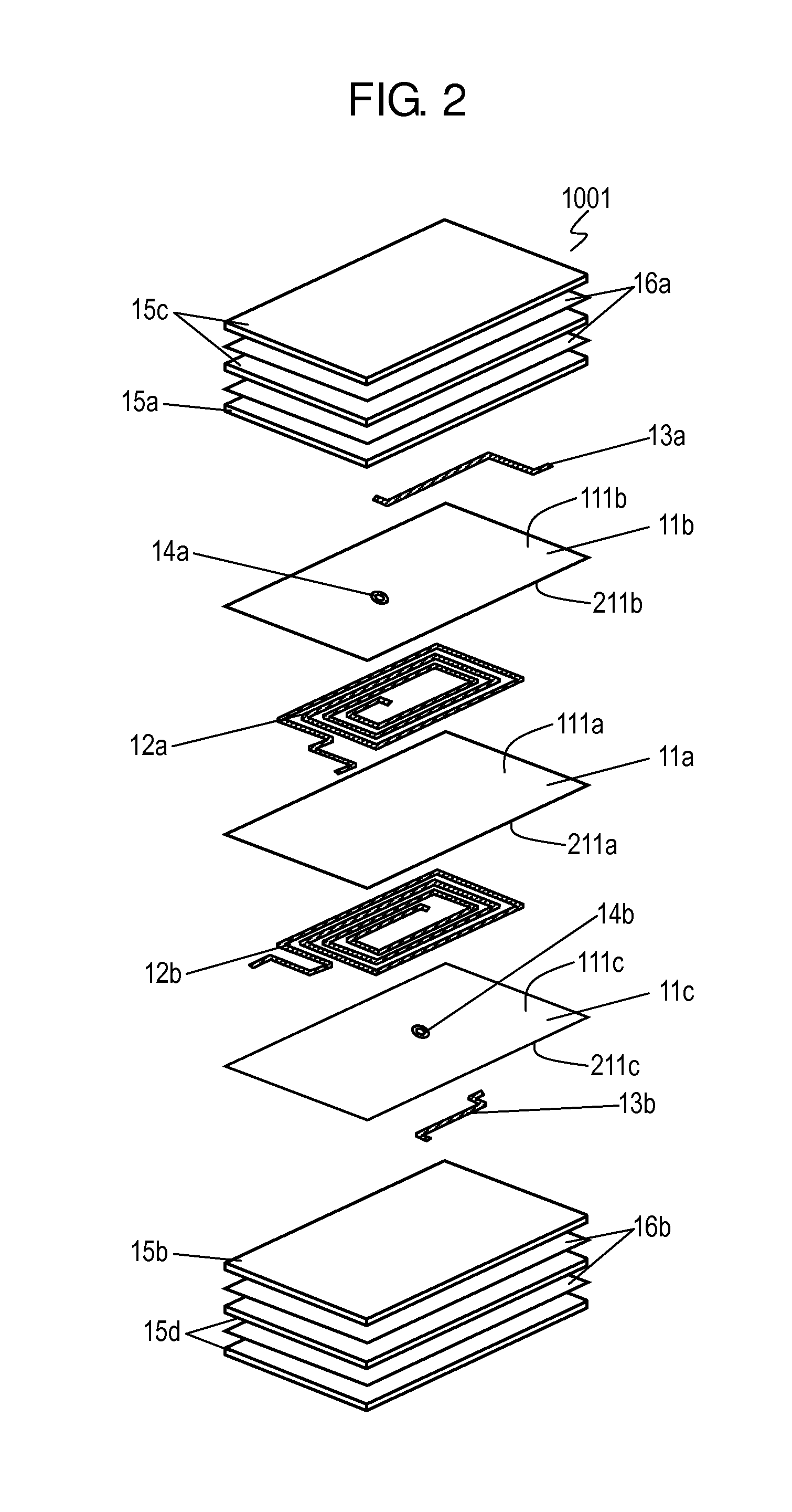
[0028]FIGS. 1 and 2 are a perspective view and an exploded perspective view of common mode noise filter 1001 in accordance with Exemplary Embodiment 1 of the present invention. FIG. 3 is a cross-sectional view of common mode noise filter 1001 at line 3-3 shown in FIG. 1.

[0029]Common mode noise filter 1001 includes insulating layer 11a, coil conductor 12a disposed on upper surface 111a of insulating layer 11a, insulating layer 11b disposed on upper surface 111a of insulating layer 11a to contact coil conductor 12a to cover coil conductor 12a, coil conductor 12b disposed on lower surface 211a of insulating layer 11a, insulating layer 11c disposed on lower surface 211a of insulating layer 11a to contact coil conductor 12b to cover coil conductor 12b, magnetic oxide layer 15a disposed on upper surface 111b of insulating layer 11b, magnetic oxide layer 15b disposed on lower surface 211c of insulating layer 11c, leading electrode 13a electrically connected to coil conductor 12a, via-elect...

exemplary embodiment 2

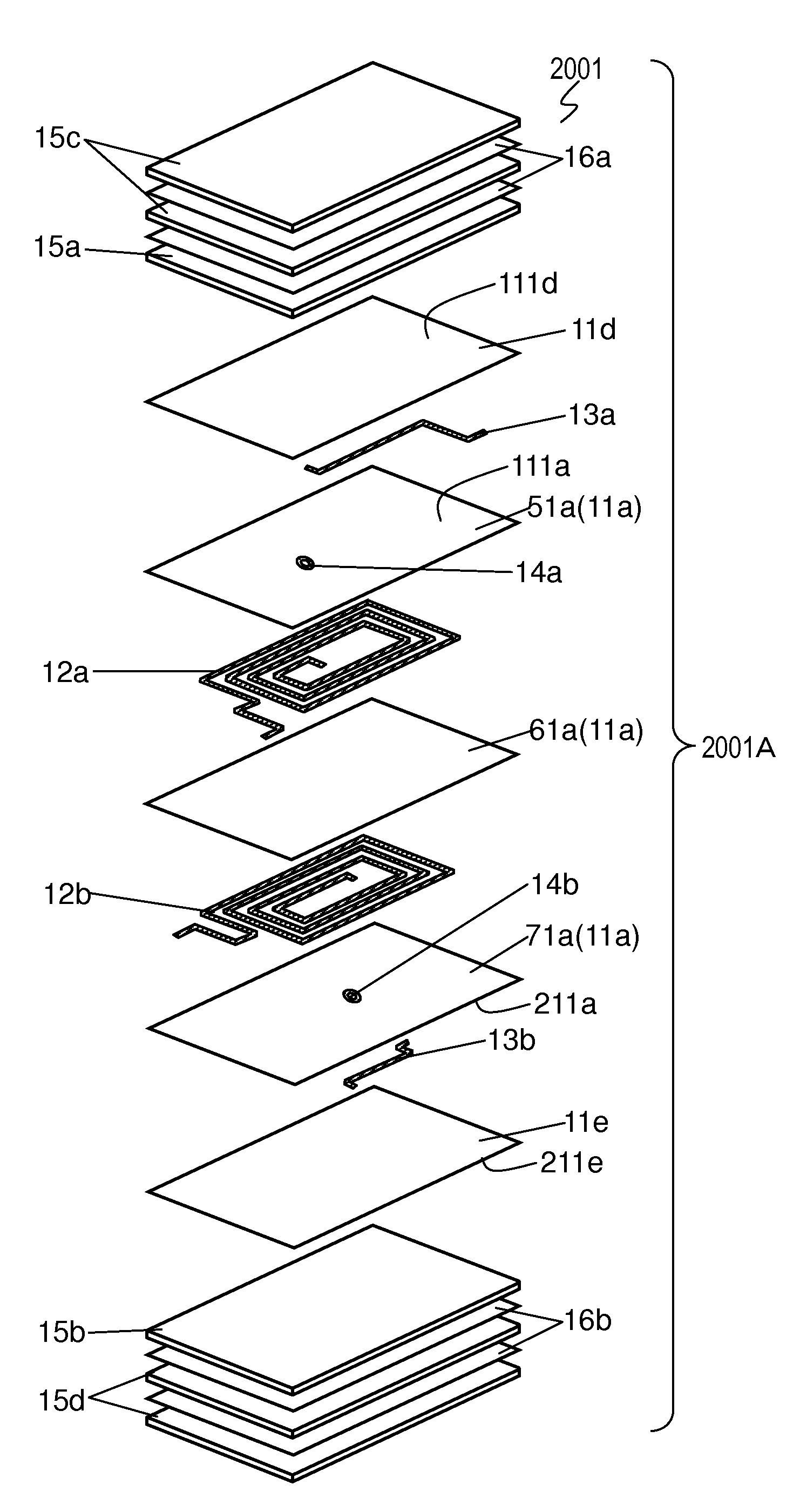
[0077]FIG. 8 and FIG. 9 are a perspective view and an exploded perspective view of common mode noise filter 2001 in accordance with Exemplary Embodiment 2 of the present invention. FIG. 10 is a cross-sectional view of common mode noise filter 2001 at line 10-10 shown in FIG. 8. In FIGS. 8 to 10, components identical to those of common mode noise filter 1001 shown in FIGS. 1 to 3 are denoted by the same reference numerals.

[0078]In common mode noise filter 2001 in accordance with Embodiment 2, coil conductors 12a and 12b are embedded in insulating layer 11a so as not to expose coil conductors 12a and 12b to upper surface 111a or lower surface 211a of insulating layer 11a. Common mode noise filter 2001 includes insulating layer 11d disposed on upper surface 111a and insulating layer 11e disposed on lower surface 211a of insulating layer 11a instead of insulating layers 11b and 11c of common mode noise filter 1001 shown in FIGS. 1 to 3.

[0079]Common mode noise filter 2001 includes insula...


PUM

PropertyMeasurementUnit
thicknessesaaaaaaaaaa
dielectric constantaaaaaaaaaa

Abstract

A common mode noise filter includes a first insulating layer, a first coil conductor on an upper surface of the first insulating layer, a second coil conductor on a lower surface of the first insulating layer, a second insulating layer on the upper surface of the first insulating layer to cover the first coil conductor, a third insulating layer on a lower surface of the second insulating layer to cover the second coil conductor. The first insulating layer contains glass and inorganic filler, and contains pores dispersed therein. The second insulating layer covers the first coil conductor, contains glass and inorganic filler, and contains pores dispersed therein. The third insulating layer covers the second coil conductor, contains glass and inorganic filler, and contains pores dispersed therein. This common mode noise filter has excellent high-frequency characteristics at a high yield rate.

Description

TECHNICAL FIELD[0001]The present invention relates to a common mode noise filter having a pair of coil conductors sandwiched by magnetic substrates, and it also relates to a method for manufacturing the same filter.BACKGROUND ART[0002]In recent years, a high-speed interface, such as a universal serial bus (USB) and an high-definition multimedia interface (HDMI), has been upgraded to work with a higher speed. This market trend invites a problem of how to deal with radiated noise. A common mode noise may cause the unintended noises, so that the market may demand a common mode noise filter working at the higher frequency in order to remove common mode noises.[0003]The common mode noise filter includes two coils wound in the same direction. An electric current flowing through a coil generates a magnetic field, so that a self-inductance produces a braking effect.[0004]The two coils of the common mode noise filter utilize an interaction between the coils for preventing an electric current...

Claims


Application Information

Patent Timeline
Patent Type & Authority Applications(United States)
IPC IPC(8): H01F27/28
CPCH01F27/2804H01F17/0013H01F2017/0066H01F2017/0093
Inventor YOSHIDA, NORITAKA
Owner PANASONIC INTELLECTUAL PROPERTY MANAGEMENT CO LTD
Why Eureka
Try Eureka