Image capturing apparatus and method for controlling the same

a technology of image capturing and image sensor, which is applied in the field of image capturing apparatus, can solve the problems of individual pd signals, affecting the image sensor yield, and affecting the accuracy of phase difference detection, so as to prevent a reduction in the yield of image sensor

Active Publication Date: 2014-07-10
CANON KK
View PDF7 Cites 60 Cited by
  • Summary
  • Abstract
  • Description
  • Claims
  • Application Information

AI Technical Summary

Benefits of technology

[0009]The present invention has been made in consideration of the above situation, and enables phase difference detection without generating a deviation and prevents a reduction in the yield of the image sensor in the case where a defective line is present in an image for phase difference detection but not in an image for viewing.

Problems solved by technology

However, in the case of using a two-dimensional detection area, if a defective line containing consecutive defective pixels in the column direction is included among the lines in the detection area, this will generate a deviation in the results of the phase difference detection and the accuracy of the phase difference detection will decrease.
In these readout methods, there may be a case in which the signal obtained by adding the two PD signals of a pixel is normal, but the individual PD signals are defective.
Specifically, this happens when two PD signals are read out in combination with each other due to a defect that occurs when the first PD signal is to be read out.
In other words, this results in not being able to obtain the first PD signal as well as the second PD signal even if the first PD signal is subtracted from the added PD signals.

Method used


Image

  • Image capturing apparatus and method for controlling the same
  • Image capturing apparatus and method for controlling the same
  • Image capturing apparatus and method for controlling the same

Examples


first embodiment

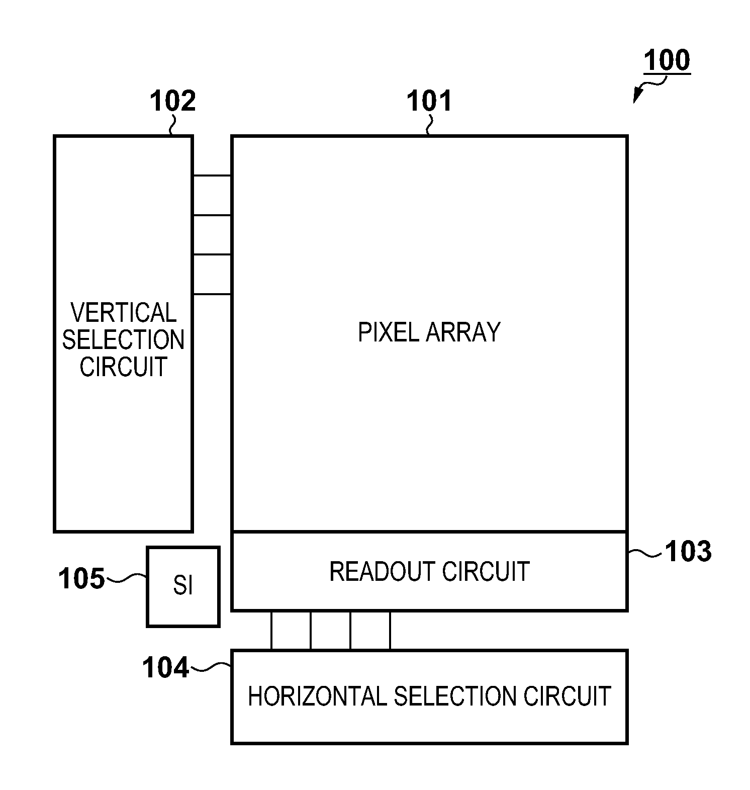
[0031]A first embodiment of the present invention will be described below with reference to the drawings. FIG. 1 is a diagram showing an overview of an image sensor 100 according to the first embodiment. The image sensor 100 in FIG. 1 includes a pixel array 101 in which multiple pixels are arrayed two-dimensionally, a vertical selection circuit 102 for selecting lines in the pixel array 101, and a horizontal selection circuit 104 for selecting columns in the pixel array 101. Also, the image sensor 100 may include a readout circuit 103 that reads out signals from a pixel selected by the vertical selection circuit 102 from among the pixels in the pixel array 101, and a serial interface (SI) 105 for determining the operation mode and the like of circuits from an external device. The readout circuit 103 has a memory that temporarily accumulates signals, a gain amp, an A / D converter, and the like. Normally, the vertical selection circuit 102 selects multiple lines of the pixel array 101 ...

modified example

[0068]With reference to FIG. 13, a description will be given of a focus detection calculation used in place of the focus detection calculation that was described with reference to FIG. 11. In the present modified example, processing for achieving a high degree of accuracy in the focus detection calculation excluding the normalization processing of step S1113 will be described. Unlike the processing shown in FIG. 11, if it is determined in step S1102 that the selected line is a defective line, the procedure up to step S1110 is skipped in the processing shown in FIG. 13. Accordingly, since the processing for clearing C(Iy) in step S1104 is skipped, correlation waveform data for the line preceding the defective line remains when the correlation waveform C(Iy) of the defective line is to be added to the correlation waveform C(I). In other words, the defective line data is interpolated using the data of the previous line. A prerequisite for performing this processing is that defective li...

second embodiment

[0070]A second embodiment of the present invention will be described next. The configuration of the image sensor in the second embodiment is similar to that of the above-described first embodiment, and therefore the description thereof will not be repeated here.

[0071]In the second embodiment, a description will be given of a system that detects a defective line while performing the focus detection calculation rather than excluding the defective line that was detected in advance from the focus detection calculation. FIG. 14 is a system configuration diagram including the image sensor involved in phase difference detection. Although the general image signals and the A image signal are output from the image sensor 100 as described above, these signals may be output at the same time and they may be output in a time series. A focus detection circuit 1400 according to the second embodiment has a B image generation unit 1401, a calculation unit 1402, and a defective line detection unit 140...


PUM


Abstract

An image capturing apparatus comprises: an image sensor that includes a plurality of pixels, each including a plurality of photoelectric conversion elements; a readout unit that reads out a signal from a portion of the photoelectric conversion elements of each pixel as a first signal and reads out a sum of signals from the plurality of photoelectric conversion elements of each pixel as an image signal; a generation unit that generates a second signal for each pixel using the image signal and the first signal; and a calculation unit that calculates a moving amount of a focus lens for achieving an in-focus state based on a phase difference between the first signal and the second signal. The calculation unit performs the calculation without using a signal from a defective line.

Description

BACKGROUND OF THE INVENTION[0001]1. Field of the Invention[0002]The present invention relates to an image capturing apparatus and a method for controlling the same, and more specifically relates to an image capturing apparatus that performs focus detection using signals from pixels capable of receiving light that passes through different pupil areas of an imaging lens, and a method for controlling the same.[0003]2. Description of the Related Art[0004]Conventionally, there are techniques for focus detection using a phase difference method at the same time as imaging by means of a configuration in which the pixels in an image sensor receive light that has passed through a different pupil area of an imaging lens. Japanese Patent Laid-Open No. 2001-083407 and Japanese Patent Laid-Open No. 2001-250931 disclose configurations in which, by providing photodiodes (PD) for receiving light collected by one micro-lens in a pixel, each photodiode receives light that passes through different pupi...

Claims


Application Information

Patent Timeline
Patent Type & Authority Applications(United States)
IPC IPC(8): H04N5/232
CPCH04N5/23212H04N23/672H04N25/68H04N25/704H04N25/75H04N25/60G02B13/0015
Inventor KISHI, TAKAFUMI
Owner CANON KK
Why Eureka
Try Eureka