Substrate carrying apparatus, substrate carrying method, and coating and developing apparatus

a carrying apparatus and substrate technology, applied in the direction of printers, instruments, photosensitive materials, etc., can solve the problems of carrying error, difficult to remove micro-water drops, and the principle of occurrence of such particles is now under investigation, so as to facilitate the removal of liquid remaining, the effect of reducing the difficulty of micro-water drops

Inactive Publication Date: 2009-07-21
TOKYO ELECTRON LTD
View PDF5 Cites 16 Cited by
  • Summary
  • Abstract
  • Description
  • Claims
  • Application Information

AI Technical Summary

Benefits of technology

[0016]The present invention was made to solve the aforementioned problem, and an object thereof is to provide a substrate carrying apparatus and a substrate carrying method, which can control contamination, such as reattachment of a liquid drop which has been attached to the rear face of a substrate to the same substrate, during a carrying operation of the substrate which has been subjected to a dipping exposure process. Another object of the present invention is to provide a coating and developing apparatus, which can control substrate contamination due to a dipping exposure process by providing such a substrate carrying apparatus in an interface, thereby avoiding lowering of the yield.
[0030]The substrate carrying apparatus of the present invention is configured such that the supporting portions support a region inside the periphery of the rear face of the substrate which has been subjected to a dipping exposure process, and a liquid receiver is provided between each supporting portion and each restricting portion for restricting the peripheral position of the wafer. Therefore, the liquid attached to the peripheral portion (the periphery or portions around it) of the rear face of the substrate can fall into each liquid receiver. Accordingly, even though repeated substrate carrying operations are performed and hence the liquid drop is accumulated in each liquid receiver, there is no risk that the periphery of the wafer W would collide with the liquid receivers, and therefore scattering in the air of the liquid drop and hence its reattachment to the surface of the wafer can be controlled.
[0031]The positional control of the substrate can be achieved by using the one-side restricting portion as well as by pressing the substrate from behind using the pressing means after the substrate has been placed on the arm body. In this way, the substrate can be always placed at a predetermined position, attaining the so-called automatic alignment, thereby providing a secure carrying operation for the wafer. In this case, the benefit obtained from providing the liquid receivers becomes quite significant because the collision of the substrate with the one-side restricting portion can be securely performed.
[0032]Furthermore, the provision of the suction port in each liquid receiver can facilitate removal of the liquid remaining on the liquid receiver, thereby controlling reattachment of the liquid to the substrate surface or occurrence of particles due to accumulation of liquid drops. Additionally, the gas discharging port in each liquid receiver can securely remove a liquid drop attached to the rear face of the substrate. If the water absorbing member is further provided in each liquid receiver, the liquid can be absorbed and eliminated from the liquid receiver with higher efficiency. Accordingly, this is also effective. Of course, various combinations of these techniques (the suction port, gas discharging port and water-absorbing member) can also be effective.

Problems solved by technology

Although it may be possible to wash the wafer W prior to heating, it is quite difficult to remove micro-water drops.
Furthermore, there may be a risk that the wafer W sticks to the arm body 13 due to the surface tension of the liquid 18, resulting in jumping of the wafer W from the arm body 13 upon transferring the wafer W toward the processing block, thereby causing a carrying error.
However, the principle of occurrence of such particles is now under investigation.

Method used


Image

  • Substrate carrying apparatus, substrate carrying method, and coating and developing apparatus
  • Substrate carrying apparatus, substrate carrying method, and coating and developing apparatus
  • Substrate carrying apparatus, substrate carrying method, and coating and developing apparatus

Examples


examples

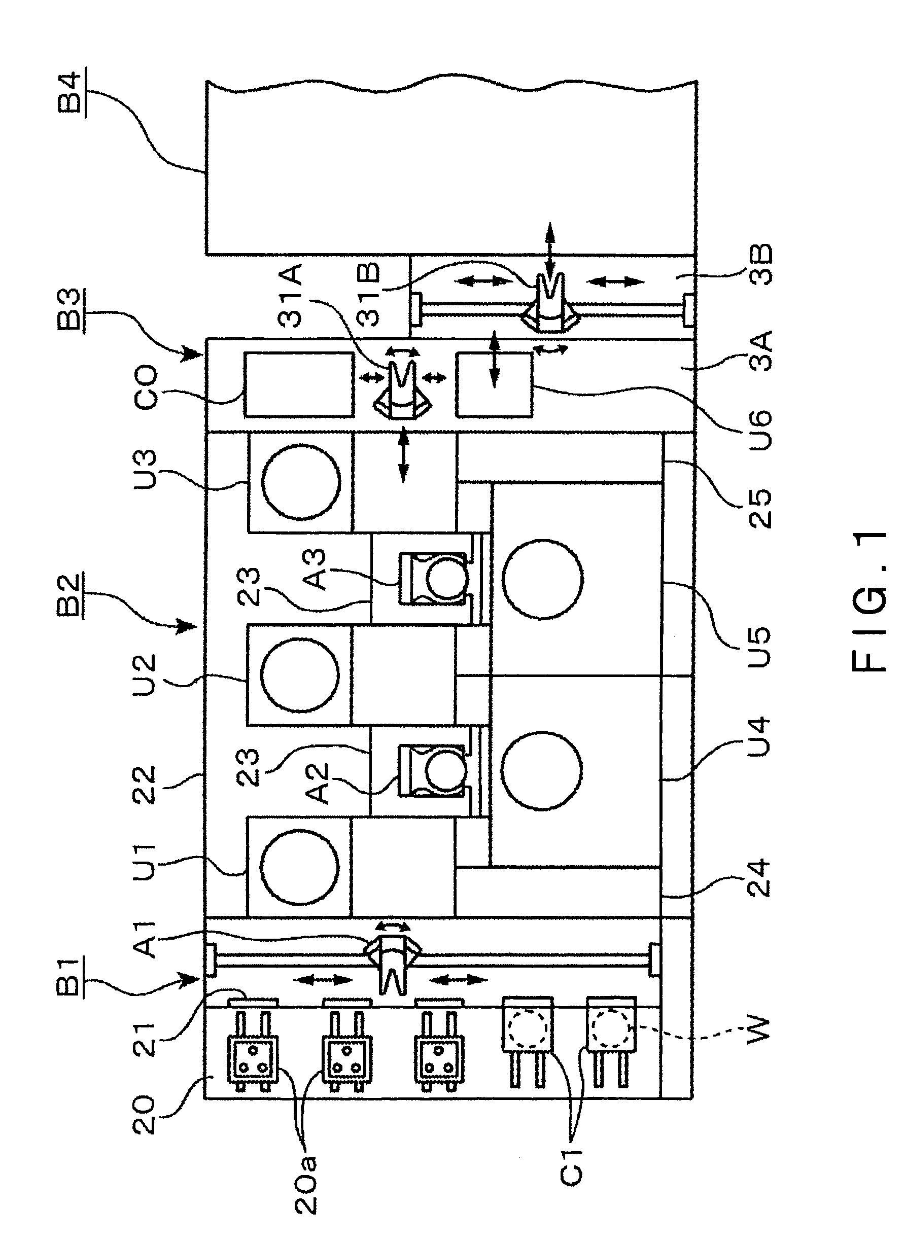
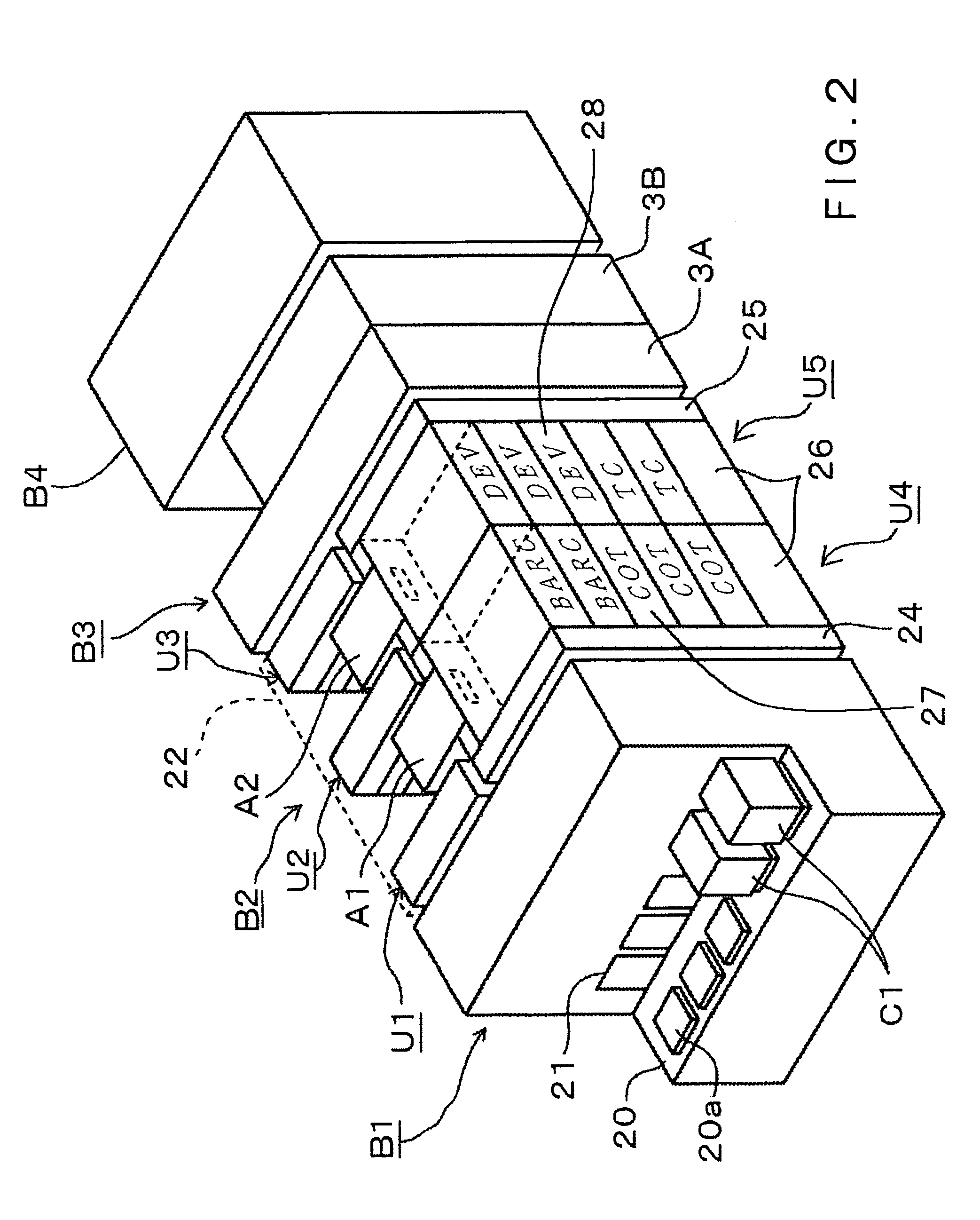
[0048]One embodiment of the present invention will be briefly described with reference to FIGS. 1 and 2 with respect to the entire construction which is applied to a system for performing a dipping exposure process. This system is composed by connecting a coating and developing apparatus with an exposure machine. In the drawings, reference character B1 designates a carrier placing unit. The carrier placing unit B1 comprises a carrier station 20 including placing portions 20a for carrying in and carrying out carriers C1 in each of which, for example, thirteen pieces of wafers W are contained airtightly, opening and closing portions 21 provided at a wall located on the front side when viewed from the carrier station 20, and a transfer mean A1 for taking out the wafer W from each carrier C1 via the corresponding opening and closing portion 21.

[0049]On the back side of the carrier placing unit B1, a treating unit B2 surrounded by a housing 22 is provided. The treating unit B2 includes r...


PUM

PropertyMeasurementUnit
wavelengthaaaaaaaaaa
lengthaaaaaaaaaa

Abstract

A substrate carrying apparatus includes an arm body; supporting portion provided in the arm body and adapted to support a region inside the periphery of the rear face of the substrate; a one-side restricting portion and an other-side restricting portion provided at opposite positions across the periphery of the substrate to restrict the peripheral positions of the substrate; and liquid receivers provided between each supporting portion and each restricting portion. A liquid drop attached to the rear peripheral portion of the substrate flows down on the bottom face of each liquid receiver. Even though repeated substrate carrying operations are performed and thus the liquid drop is accumulated in each liquid receiver, there is no risk that the liquid drop in each liquid receiver would be scattered in the air by the action of the periphery of the substrate and hence the scattered liquid would be attached again onto the surface of the substrate.

Description

BACKGROUND OF THE INVENTION[0001]1. Field of the Invention[0002]The present invention relates to a substrate carrying apparatus, a substrate carrying method, and a coating and developing apparatus equipped with the substrate carrying apparatus, for carrying substrates having subjected to a process in which a liquid remains on a periphery of the rear face of each substrate, such as a dipping exposure process.[0003]2. Background Art[0004]Conventionally, in a photo-resist process, which is one of the processes for manufacturing semiconductors, semiconductor wafers (hereinafter referred to as wafers) are coated with a resist on their surfaces; and the resist is exposed to light through a predetermined pattern, and thereafter a developing liquid is supplied to the wafers to develop and form a resist pattern. This process is performed using a system in which an exposure machine is connected to a processing block of a coating and developing apparatus generally including a coating unit and ...

Claims


Application Information

Patent Timeline
Patent Type & Authority Patents(United States)
IPC IPC(8): G03D5/00C23C16/18G03B27/52
CPCG03D3/08H01L21/68707H01L21/67126Y10S414/141G03F7/70341G03F7/7075G03F7/30G03F7/2041G03F7/70733G03F7/70916
Inventor NAKAHARADA, MASAHIROISHIDA, SEIKIYAMAMOTO, TAROMORIKAWA, KATSUHIRO
Owner TOKYO ELECTRON LTD
Why Eureka
Try Eureka