Display device and method for manufacturing the same

Active Publication Date: 2013-10-31
TRIVALE TECH
View PDF4 Cites 16 Cited by
  • Summary
  • Abstract
  • Description
  • Claims
  • Application Information

AI Technical Summary

Benefits of technology

[0011]It is an object of the present invention to provide a display device capable of stably forming various kin

Problems solved by technology

However, the aluminum alloy is high in reflectivity, and the problem is that incident light reflects on an aluminum alloy wiring, in the environment having the large amount of the incident light from the outside of the display device, so that preferable display characteristics cannot be obtained.
Meanwhile, in the case where the antireflective film is formed on the wiring in order to reduce the reflection of the light inputted from the outside as described above, when an identification (ID) mark to identify a panel or an array substrate in steps of forming the wiring is to be

Method used


Image

  • Display device and method for manufacturing the same
  • Display device and method for manufacturing the same
  • Display device and method for manufacturing the same

Examples


first preferred embodiment

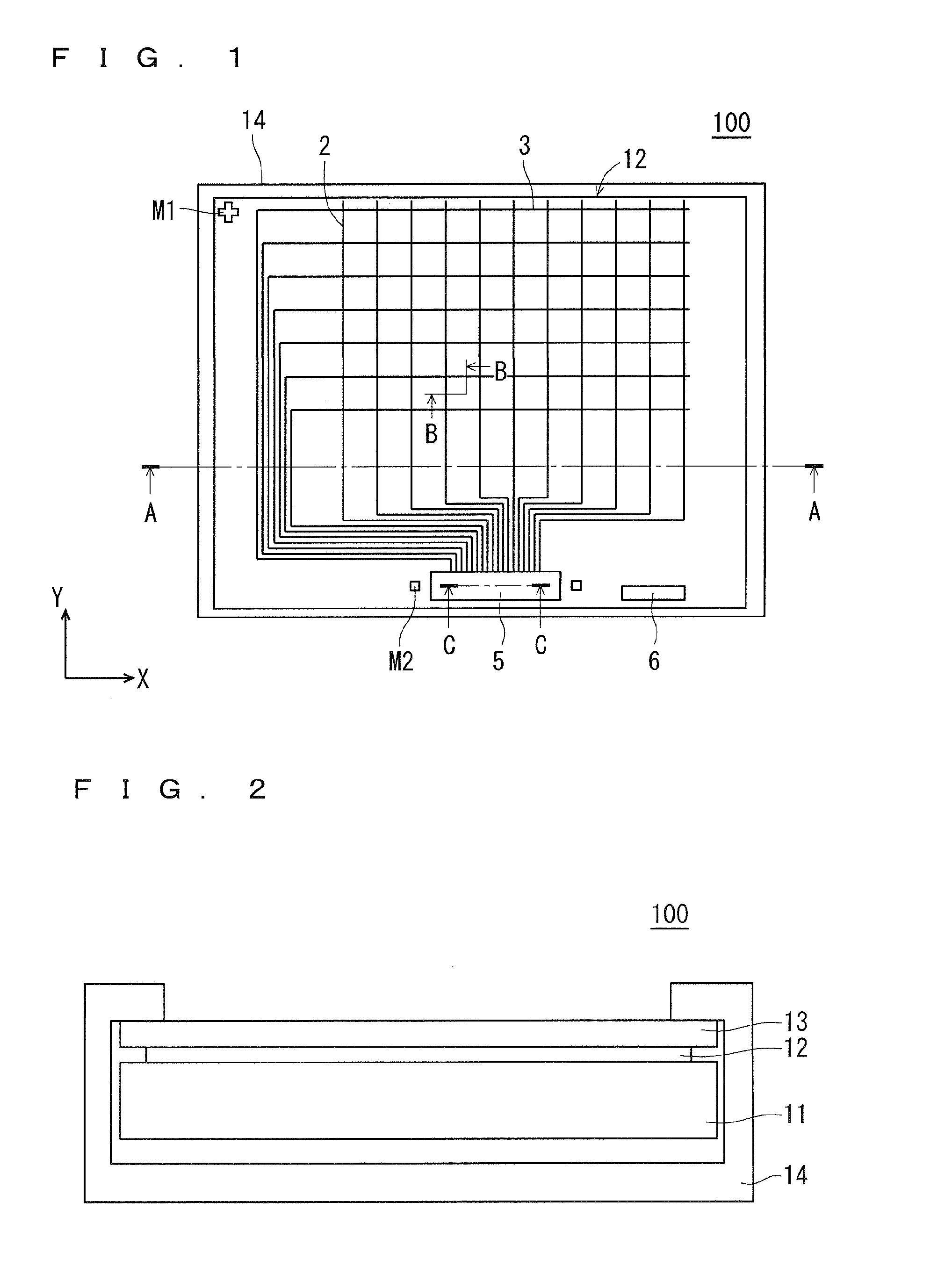
[0059]Hereinafter, a first preferred embodiment according to the present invention will be described with reference to cross-sectional configurations of the touch panel 12. FIG. 4 is a view showing one cross-sectional configuration of the touch panel 12 taken along a line B-B in FIG. 1.

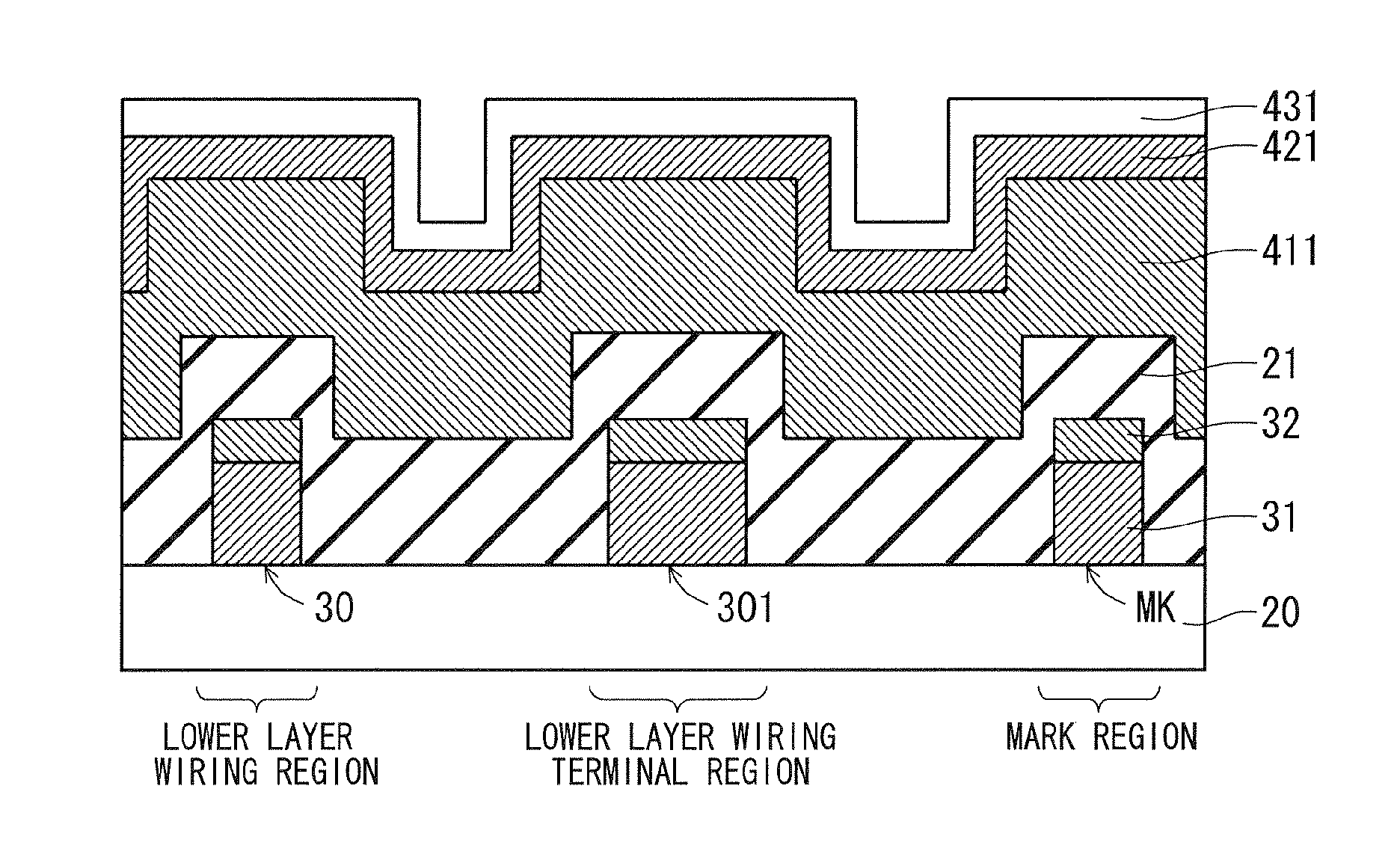
[0060]As shown in FIG. 4, the touch panel 12 has a configuration in which a lower layer wiring 30 is formed of laminated films of a low-resistance conductive film 31 serving as a lower layer, and a low-reflection film 32 serving as an upper layer, on a transparent substrate 20 (equivalent to the mother substrate) composed of glass or PET, and an interlayer insulating film 21 is provided so as to cover the lower layer wiring 30. The lower layer wiring 30 corresponds to the X position detecting wiring 2 shown in FIG. 1. In addition, the transparent substrate 20 serves as a base for forming the lower layer wiring 30, so that it is referred to as a base layer occasionally. Furthermore, the low-reflection ...

second preferred embodiment

[0143]Next, a second preferred embodiment according to the present invention will be described with reference to FIG. 25 to FIG. 30. FIG. 25 is a view corresponding to a state in which the resist mask shown in FIG. 18 in the first the present invention is removed. In addition, as for the same configuration as in FIG. 18, the same reference is affixed thereto and its description is omitted.

[0144]As shown in FIG. 25, each of a lower layer wiring terminal 301B and a mark kind MK2 does not have the low-reflection film 32. The contact hole CH1 provided above the lower layer wiring terminal 301B penetrates the interlayer insulating film 21 and the protective film 22 and reaches the low-resistance conductive film 31, and the contact hole CH2 provided above the upper layer wiring terminal 401 penetrates the protective film 22 and reaches the low-resistance conductive film 41. In addition, the contact hole is not provided above the mark kind MK2. The contact hole may not be provided above th...

third preferred embodiment

[0173]Next, a third preferred embodiment according to the present invention will be described with reference to FIG. 34 to FIG. 45. FIG. 34 is a view corresponding to a state in which the resist mask shown in FIG. 18 in the first preferred embodiment is removed, and in the lower layer wiring 30A, the transparent cap film 33A is arranged on the low-reflection film 32, and in the upper layer wiring 40A, the transparent cap film 43A is arranged on the low-reflection film 42. In addition, as for the same configuration as in FIG. 18, the same reference is affixed thereto and its description is omitted.

[0174]Each of the contact holes CH1 and CH3 provided above the lower layer wiring terminal 301 and the mark kind MK, respectively penetrates the low-reflection film 32 and reaches the low-resistance conductive film 31, and the contact hole CH2 provided above the upper layer wiring terminal 401 penetrates the low-reflection film 42 and reaches the low-resistance conductive film 41. For examp...


PUM


Abstract

A display device includes a laminated wiring formed of a low-resistance conductive film, and a low-reflection film mainly containing Al and functioning as an antireflective film which are sequentially arranged on a transparent substrate, a wiring terminal part provided at an end part of the laminated wiring and has the same laminated structure as that of the laminated wiring, and an insulating film for covering the laminated wiring and the wiring terminal part, in which the insulating film side serves as a display surface side, the wiring terminal part has a first opening part penetrating the insulating film and the low-reflection film and reaching the low-resistance conductive film, and an outer peripheral portion of the first opening part has a laminated structure of the low-resistance conductive film, the low-reflection film, and the insulating film, in at least one part.

Description

BACKGROUND OF THE INVENTION[0001]1. Field of the Invention[0002]The present invention relates to a display device and a method for manufacturing the same and more particularly, relates to a display device suitable for being used outdoors.[0003]2. Description of the Background Art[0004]As for the display device used outdoors, preferable display characteristics are required in an environment having a large amount of incident light from an outside of the display device such as a case where it is used under sunlight. Meanwhile, a wiring of the display device is required to be low in resistance and easily processed, so that an aluminum (Al) alloy is increasingly used as metal which satisfies the above requirement.[0005]However, the aluminum alloy is high in reflectivity, and the problem is that incident light reflects on an aluminum alloy wiring, in the environment having the large amount of the incident light from the outside of the display device, so that preferable display characteris...

Claims


Application Information

Patent Timeline
IPC IPC(8): H01L33/44
CPCH01L33/44G02F1/1345G02F1/13458G02F1/136286G06F3/0445G02F1/13629G02B1/116G06F2203/04103G06F2203/04111G06F2203/04112H05K1/0269H05K1/0274H05K1/0298
Inventor HAYASHI, MASAMIMIYAMOTO, KENICHIYAMAYOSHI, KAZUSHITSUCHIMICHI, JUNICHI
Owner TRIVALE TECH
Why Eureka
Try Eureka