Sensor system for determining the control signals activating ciliary muscles

a sensor system and eye technology, applied in the field of eye control signals activating ciliary muscles, can solve the problems of insufficient adjustment of the radius of curvature of the eye, the inability of the eye to accommodate, and the rigidity of the eye lens, so as to achieve the effect of reducing size, reducing energy storage of the sensor system, and increasing installation spa

Active Publication Date: 2014-07-10
KARLSRUHER INST FUR TECH
View PDF2 Cites 32 Cited by
  • Summary
  • Abstract
  • Description
  • Claims
  • Application Information

AI Technical Summary

Benefits of technology

[0032]Alternatively, the sensor system comprises a preferably contact-free transmission means as interface to an external energy source and/or an external accommodating or adjustable lens system. By way of this interface, accommodation information can be transmitted to accommodating glasses or an accommodating ophthalmological system. The advantage of external components such as glasses as an adaptive optical element resides in the fact that a substantially larger installation space is available. Such glasses comprise preferably an optical element with variable refraction capability, a control unit for this optical element, an energy supply and also transmission means for the sensor system. The sensor system is supplied with energy preferably by means of the glasses. In this way, the energy storage of the sensor system

Problems solved by technology

However, with increasing age, the human eye loses its capability for accommodation, that is, the capability of the natural lens system to adapt to different distances by adjusting the curvature or focal length of the lens.
However, with increasing age, the natural lens becomes stiffer and can no longer change its radius of curvature sufficiently to provide for different focal lengths.
However, even when, with increasing age, the human eye lens becomes more rigid and can no longer adjust to different viewing distances, the ciliary muscle remains active.
With this condition, the natural lens becomes cloudy to an extent that a person

Method used


Image

  • Sensor system for determining the control signals activating ciliary muscles
  • Sensor system for determining the control signals activating ciliary muscles
  • Sensor system for determining the control signals activating ciliary muscles

Examples


Embodiment Construction

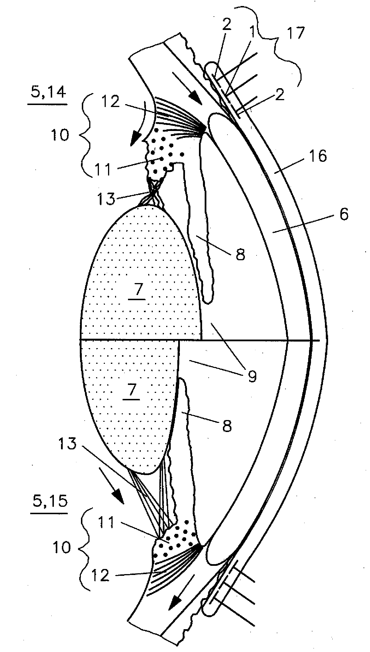
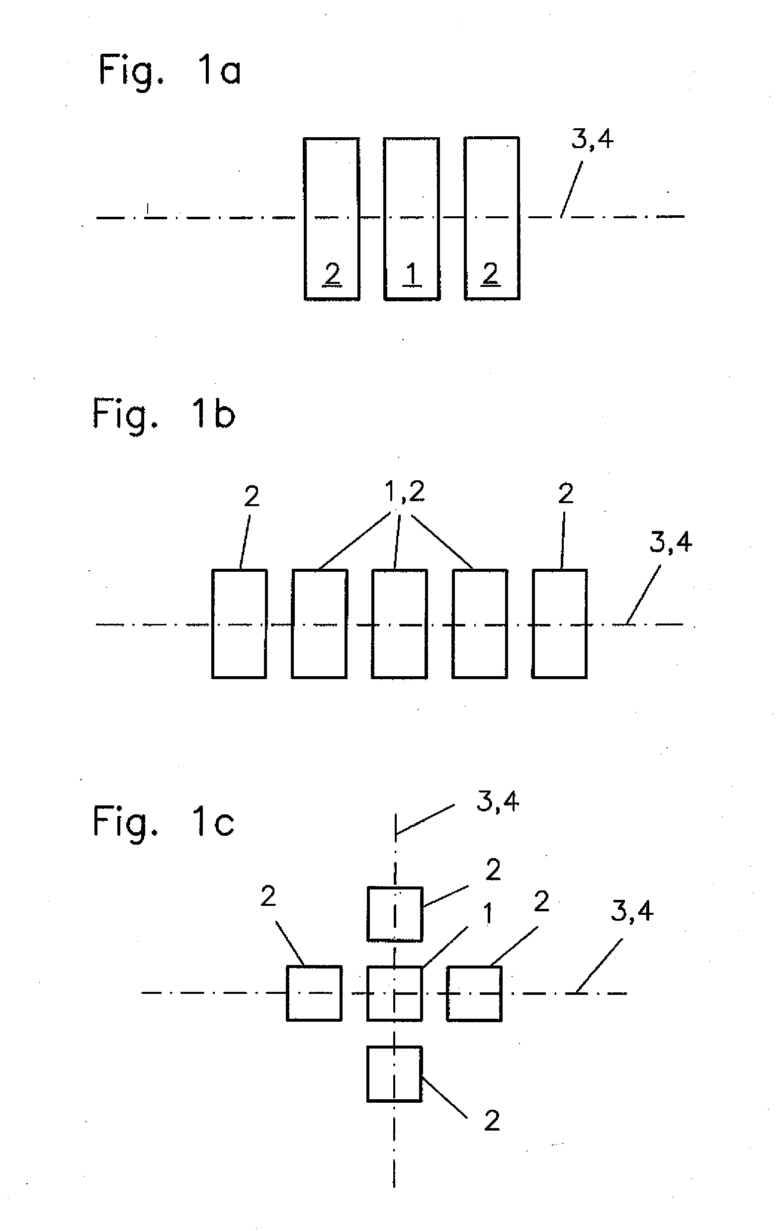
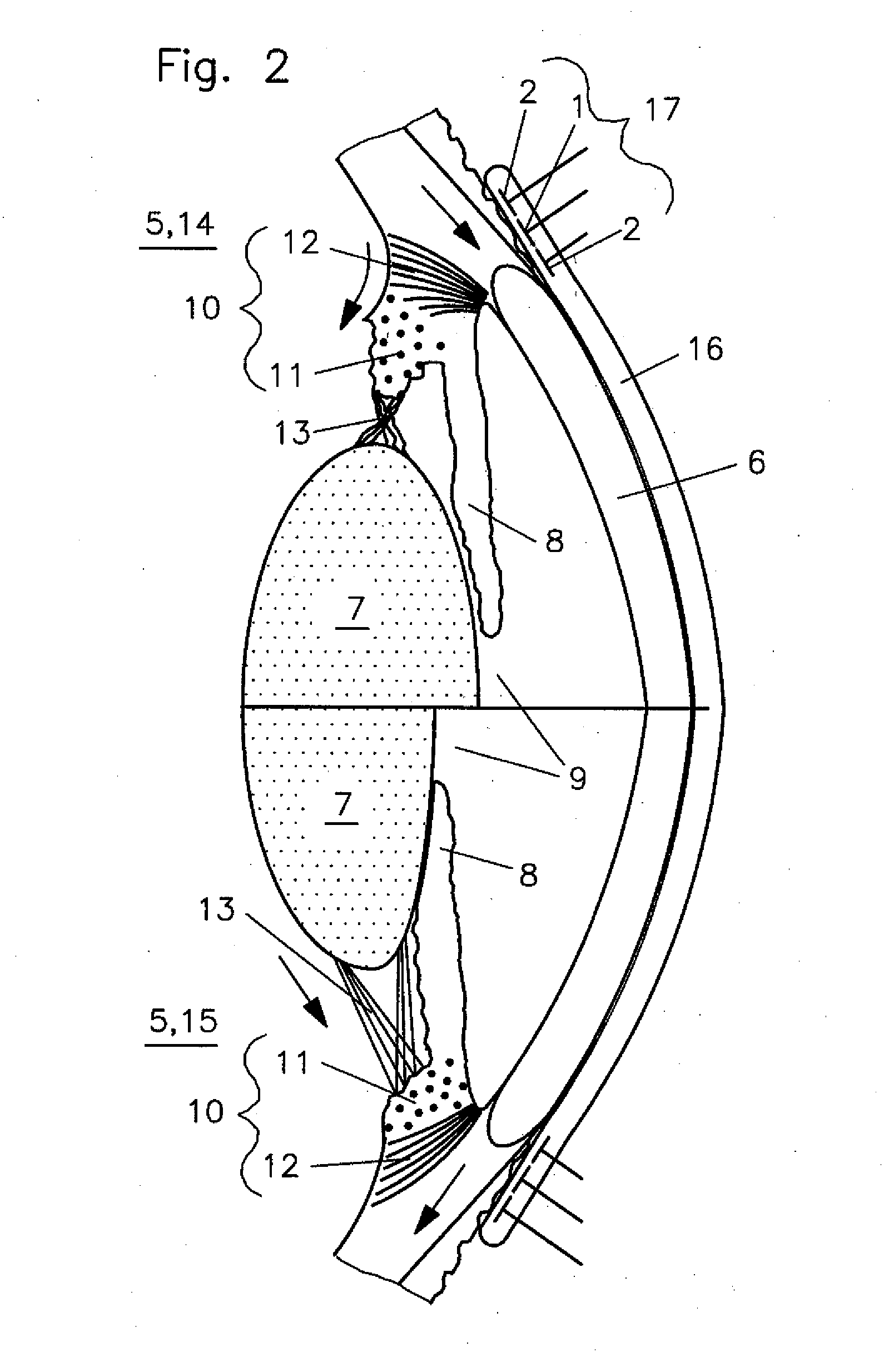
[0039]Essential elements of the sensor system are the sensors 17 with a fundamental electrode arrangement as it is shown in

[0040]FIGS. 1a to 1c in an exemplar but not limiting manner.

[0041]They comprise in each case an arrangement as shown in FIG. 1a with an intermediate electrode 1 (reference electrode) as well as at least two measuring electrodes 2 which are arranged aligned at opposite sides of the reference electrode 1. The arrangement of the measuring electrodes 2 is preferably symmetrical with regard to the intermediate electrode 1 and all are preferably arranged in a single plane symmetrically around an axis of symmetry 3 representing the orientation 4 of the sensor.

[0042]In an embodiment of the sensor system 17 as shown for example in FIG. 1b, more than three electrodes, for example five electrodes are arranged in a row around the axis of symmetry. This permits a free selection of the three adjacent electrode surface areas comprising a center electrode (reference electrode) ...


PUM


Abstract

In a sensor system for determining the control signal supplied to the ciliary muscles of an eye for adjusting the focal length of the lens of an eye, a contact element of an electrically non-conductive material and provided with sensors is disposed on the cornea of the eye so that the sensors are arranged in contact with an annular area of the cornea next to the ciliary eye muscles so as to be able to sense the focal adjustment signals supplied to the ciliary muscles and the sensed adjustment signals are supplied to a signal processing unit which provides a control signal to a lens system with adjustable focal length for adjusting the focal length thereof depending on the focal adjustment signals of the ciliary eye muscles.

Description

[0001]The invention resides in a sensor system for determining the control signals activating the ciliary muscles of an eye via a contact element which is disposable on the cornea around the iris of an eye and consists of an electrically nonconductive material on which sensors are arranged in an annular array and a signal processor arranged on or in the contact element.[0002]The sensor system includes furthermore an evaluation system for determining the accommodation needs of an artificial accommodation system preferably of an artificial lens or an ophthalmic technical system.[0003]The human eye is a natural optical system which depicts objects on the retina by way of several light refracting boundary surfaces with sharp definition. When the distance of the object being observed changes, the imaging conditions of the optical system need to adapt to maintain the sharp definition of the object. In the human eye, this is accomplished by a deformation of the lens by means of the ciliary...

Claims


Application Information

Patent Timeline
IPC IPC(8): A61B3/10G02C7/08A61B5/296
CPCG02C7/083A61B3/10A61B3/09A61F2/16A61B5/1107A61B5/6821A61F2250/0002A61F2/1624A61B5/398A61B5/297
Inventor GUTH, HELMUTGENGENBACH, ULRICHBRETTHAUER, GEORGFLIEDNER, JANBECK, CHRISTOPHKRUG, MARKUSMARTIN, THOMASNAGEL, JOERGKOKER, LIANESIEBER, INGO
Owner KARLSRUHER INST FUR TECH
Why Eureka
Try Eureka