

Electrical contact device
Inactive Publication Date: 2014-07-10
SALCOMP OYJ
View PDF10 Cites 0 Cited by
- Summary
- Abstract
- Description
- Claims
- Application Information
AI Technical Summary
Benefits of technology
The invention is an electrical contact device that allows for a safer and more compact arrangement of electrical components on a printed circuit board. The device achieves this by using a V-shaped or U-shaped design that eliminates the need for additional parts. The size of the contact pad on the printed circuit board determines the area that cannot safely connect electrical components. The distance between the safety area and the components must be at least the size of the contact pad. The invention also incorporates a coil spring with a specific design that allows for a shorter overall length while still maintaining flexibility and a robust electrical connection. The device is easy to manufacture and has proven to be more efficient in terms of space utilization compared to previous designs.
Problems solved by technology
A problem associated with the electrical contact device of FIG. 1 and other known contact devices relates to safety distances that are required from electrical components on a printed circuit board.
Especially a problem relates to safety distances that are required from primary side components around leads before a fuse resistor.
This limits the minimum achievable size of the printed circuit board and thereby the size of the electrical device, which is a problem especially in small-sized electrical devices, such as a battery charger of a mobile phone.
Another problem is that electrical contact devices of the prior art are expensive and laborious to manufacture, mainly because of their shaped parts.
Method used
View moreImage
Smart ImageViewing Examples

Examples
first embodiment
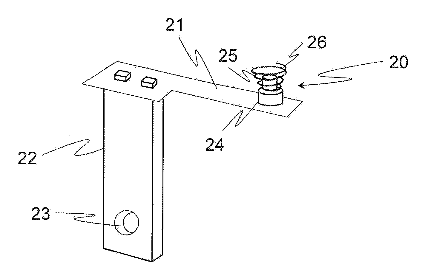
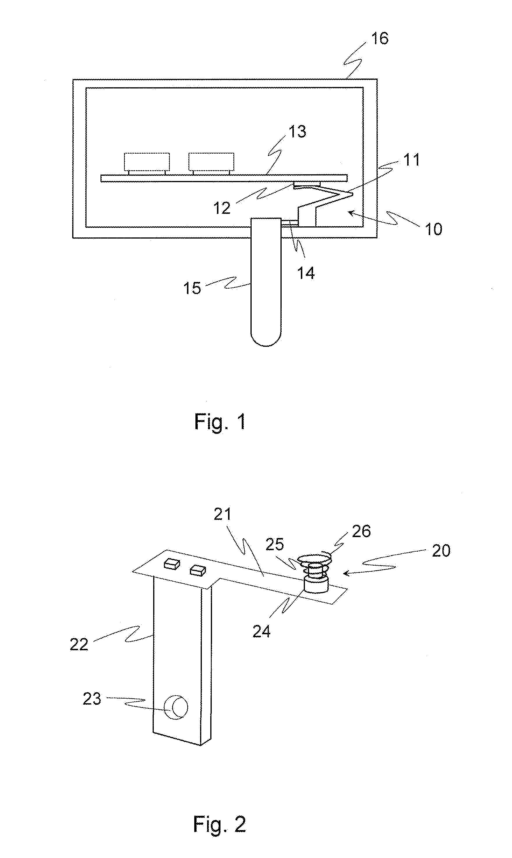
[0047]FIG. 2 illustrates an electrical contact device according to the invention,
second embodiment
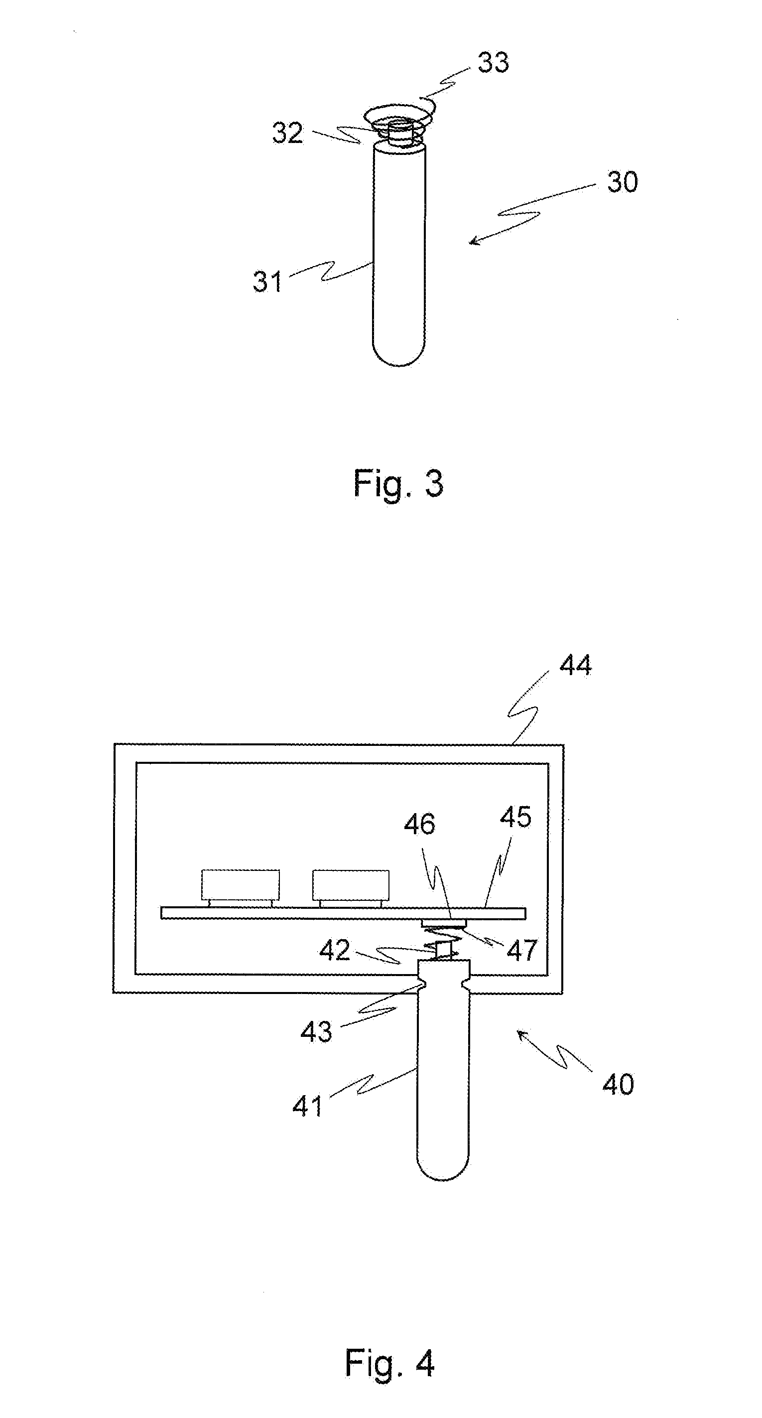
[0048]FIG. 3 illustrates an electrical contact device according to the invention,
[0049]FIG. 4 illustrates an electrical contact arrangement according to an embodiment the invention,
[0050]FIG. 5 illustrates a contact pad according to a first embodiment of the invention, and
[0051]FIG. 6 illustrates a contact pad according to a second embodiment of the invention.
Login to View More PUM
 Abstract
The present invention relates to an electrical contact device which comprises an electrically conductive base part, and an electrically conductive protruding part protruding from the electrically conductive base part. The electrical contact device also comprises an electrically conductive coil spring having a diameter that increases from a first end to a second end of the electrically conductive coil spring. The electrically conductive coil spring is arranged around the electrically conductive protruding part in such a manner that the first end of the electrically conductive coil spring faces the electrically conductive base part, and the electrically conductive coil spring extends further from the electrically conductive base part than the electrically conductive protruding part does.
Description
TECHNICAL FIELD OF THE INVENTION[0001]The present invention relates to an electrical contact device according to the preamble of the appended independent claim. The invention also relates to an electrical contact arrangement incorporating an electrical contact device according to the invention.BACKGROUND OF THE INVENTION[0002]An electrical device typically comprises a plurality of electrical contacts between electrical components and / or parts of the device. Electrical contacts may be implemented using various types of contact devices. For example, electrical components may be connected via solder joints to a printed circuit board (PCB), and the circuit board may be connected via its contact pads to contact pins, which deliver electrical current to the circuit board.[0003]An example of an electrical contact device according to the prior art for conducting electrical current to a printed circuit board is illustrated schematically as a cross section in FIG. 1. The electrical contact d...
Claims
Login to View More Application Information
Patent Timeline
 IPC IPC(8): H01R12/57
CPCH01R12/57H01R12/714H01R13/2421
InventorKAURALA, SIMO
OwnerSALCOMP OYJ