Displacement detecting device and scale

a technology of displacement detection and scale, applied in the direction of speed measurement using gyroscopic effects, converting sensor output optically, instruments, etc., can solve the problems of limited measurement range when the first reading unit or the second reading unit moves in the orthogonal direction, the detection accuracy is significantly reduced, and the displacement cannot be detected. to achieve the effect of expanding the measurable rang

Active Publication Date: 2014-07-10
DMG MORI CO LTD
View PDF3 Cites 4 Cited by
  • Summary
  • Abstract
  • Description
  • Claims
  • Application Information

AI Technical Summary

Benefits of technology

The present invention provides a displacement detecting device and scale that can measure the absolute position without using the origin mark and origin signal. This expands the measurable range of the device without being restricted by the origin mark.

Problems solved by technology

Further, in a case where the first reading unit gets away from the first region or in a case where the second reading unit gets away from the second region, it is not possible to form the origin mark, and therefore, a displacement cannot be detected.
Further, it can be thought to extend the measurement range by increasing the intervals in the first region and in the second region, but there is such a problem that detection accuracy reduces considerably when the scale tilts or when the scale expands or shrinks due to a change in temperature, etc.
However, in this case, there is also such a problem that the measurement range when the first reading unit or the second reading unit moves in the orthogonal direction is limited.

Method used


Image

  • Displacement detecting device and scale
  • Displacement detecting device and scale
  • Displacement detecting device and scale

Examples


first embodiment example

1. First Embodiment Example

[0050]First, a configuration of a displacement detecting device in a first embodiment example (hereinafter, referred to as the “present example”) of the present invention is explained in accordance with FIG. 1 to FIG. 3.

[0051]1-1. Configuration Example of Displacement Detecting Device

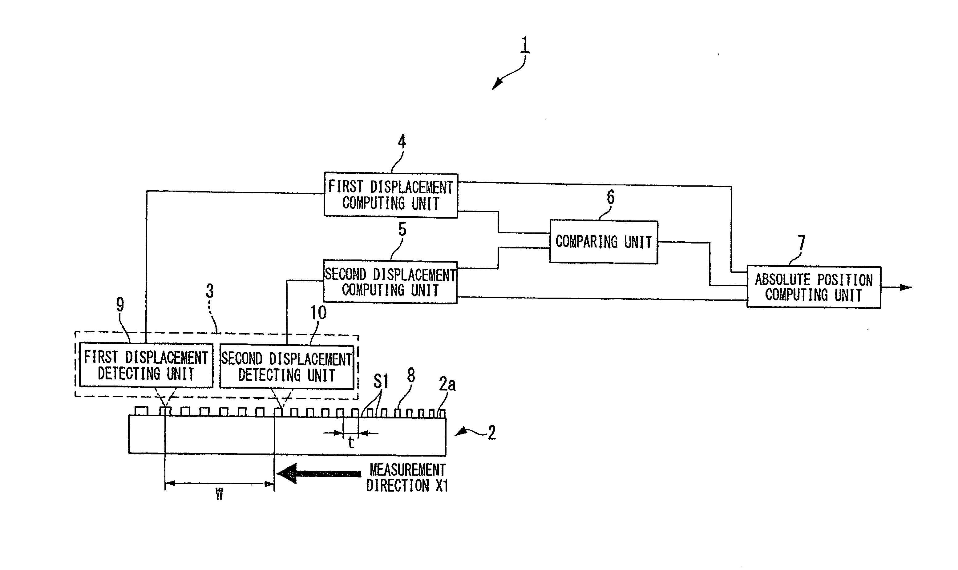
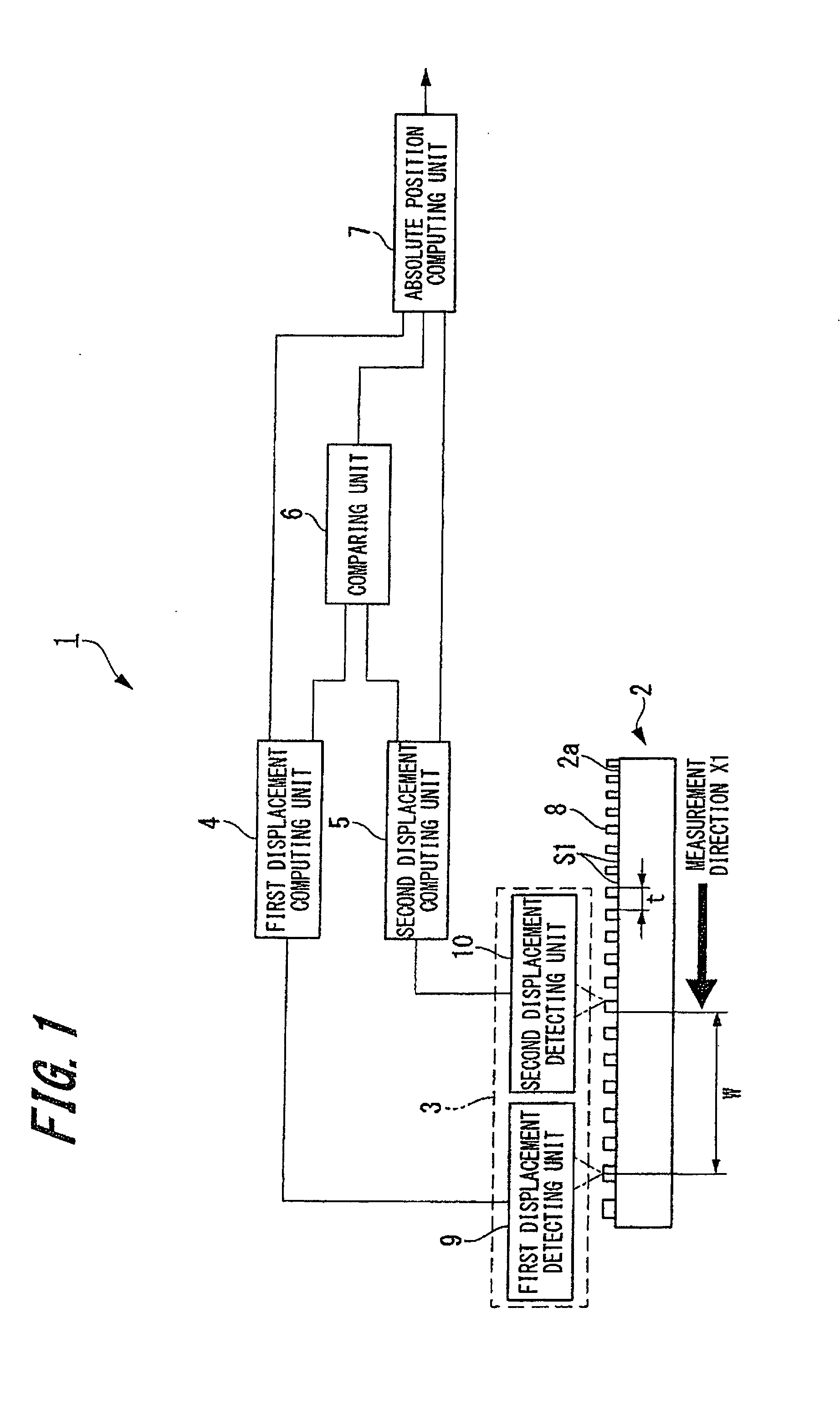
[0052]FIG. 1 is an outline configuration diagram showing a configuration of a displacement detecting device.

[0053]A displacement detecting device 1 of the present example is a displacement detecting device capable of detecting linear displacement and an absolute position with respect to a scale using a reflective diffraction grating. As shown in FIG. 1, the displacement detecting device 1 includes a scale 2, a detection head 3, a first displacement computing unit 4 and a second displacement computing unit 5 connected to the detection head 3, a comparing unit 6, and an absolute position computing unit 7.
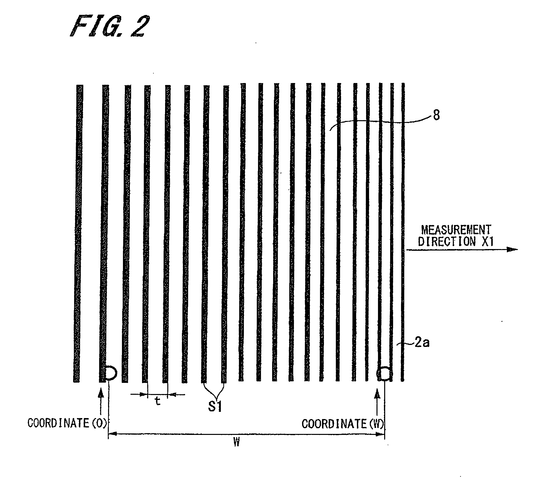
[0054][Scale]

[0055]The scale 2 is formed into the shape of substantially a ...

second embodiment example

2. Second Embodiment Example

[0172]Next, with reference to FIG. 11, a displacement detecting device according to a second embodiment example of the present invention is explained.

[0173]FIG. 11 is an outline configuration diagram showing a configuration of the displacement detecting device 40 according to the second embodiment example.

[0174]The displacement detecting device 40 according to the second embodiment example differs from the displacement detecting device 1 according to the first embodiment example in the numbers of provided displacement detecting units and displacement computing units. Because of this, the same symbols are attached to the parts common to those of the displacement detecting device 1 according to the first embodiment example and duplicated explanation is omitted here.

[0175]As shown in FIG. 11, the displacement detecting device 40 includes the scale 2, a detection head 43, a first displacement computing unit 44, a second displacement computing unit 45, a third...

third embodiment example

3. Third Embodiment Example

[0188]Next, with reference to FIG. 12, a displacement detecting device according to a third embodiment example of the present invention is explained.

[0189]FIG. 12 is an outline configuration diagram showing a configuration of the displacement detecting device 60 according to the third embodiment example.

[0190]The displacement detecting device 60 according to the third embodiment example differs from the displacement detecting device 1 according to the first embodiment example in the number of provided scales. Because of this, the same symbols are attached to the parts common to those of the displacement detecting device 1 according to the first embodiment example and duplicated explanation is omitted here.

[0191]As shown in FIG. 12, the displacement detecting device 60 has a first scale 2A, a second scale 2B, the detection head 3, the first displacement computing unit 4 and the second displacement computing unit 5 connected to the detection head 3, the comp...


PUM


Abstract

A scale has marks whose pitch interval changes along a measurement direction in a manner that can be approximated to a quadratic or higher-order polynomial. A comparing unit calculates a difference between first relative position information and second relative position information per unit displacement in a position where a first displacement detecting unit is arranged. Then, an absolute position computing unit computes an absolute position in the measurement direction with respect to the scale based on absolute position information and the relative position information of at least one of the first relative position information and the second relative position information, and outputs the absolute position.

Description

CROSS REFERENCES TO RELATED APPLICATIONS[0001]The present invention contains subject matter related to Japanese Patent Application JP 2012-268988 and Japanese Patent Application JP 2013-224094 filed in the Japanese Patent Office on Dec. 10, 2012 and Oct. 29, 2013, respectively, the entire contents of which being incorporated herein by reference.BACKGROUND OF THE INVENTION[0002]1. Field of the Invention[0003]The present invention relates to a displacement detecting device used when performing positioning and detecting an amount of displacement in the linear direction in a machine tool, an industrial machine, a robot, etc., and to a scale used in the displacement detecting device.[0004]2. Description of the Related Art[0005]Conventionally, a scale and a displacement detecting device including a detection head are used to detect an amount of linear movement and a linear position for positioning, controlling, position displaying, etc., of a machine tool, an industrial machine, a robot, ...

Claims


Application Information

Patent Timeline
Patent Type & Authority Applications(United States)
IPC IPC(8): G01B11/00
CPCG01D5/34792G01B11/00G01D5/38G01D5/34746G01D5/34723G01D2205/90G01D5/34794
Inventor TAMIYA, HIDEAKI
Owner DMG MORI CO LTD
Why Eureka
Try Eureka