Devices and methods for exhaust gas recirculation operation of an engine

a technology of exhaust gas recirculation and equipment, applied in the field of equipment, can solve the problems of increasing the cost of the engine, egr valves, and valve assemblies that are susceptible to thermal degradation, so as to improve combustion efficiency, reduce emissions, and improve knock tolerance

Active Publication Date: 2014-07-17
CMR TECH +1
View PDF15 Cites 24 Cited by
  • Summary
  • Abstract
  • Description
  • Claims
  • Application Information

AI Technical Summary

Benefits of technology

[0002]Exhaust gas recirculation (EGR) may be used in engines to decrease emissions (e.g., nitrogen oxide emissions), improve knock tolerances, improve combustion efficiency, and reduce throttling losses. EGR may be employed in engines utilizing compression or spark ignition. EGR system may flow exhaust gas from one or more of the cylinders in the engine to the engine's intake system via an EGR conduit. EGR valves may be disposed in EGR conduits to regulate exhaust gas flow through the conduits.

Problems solved by technology

For example, the valve assemblies may be susceptible to thermal degradation from the high temperature exhaust gases flowing therethrough.
Additionally, the EGR valves may be costly, thereby increasing the engine's cost.
Moreover, the valve assemblies may increase losses in the EGR conduit as well as the exhaust system, while the exhaust conduits themselves decrease the compactness of the engine.

Method used


Image

  • Devices and methods for exhaust gas recirculation operation of an engine
  • Devices and methods for exhaust gas recirculation operation of an engine
  • Devices and methods for exhaust gas recirculation operation of an engine

Examples


Embodiment Construction

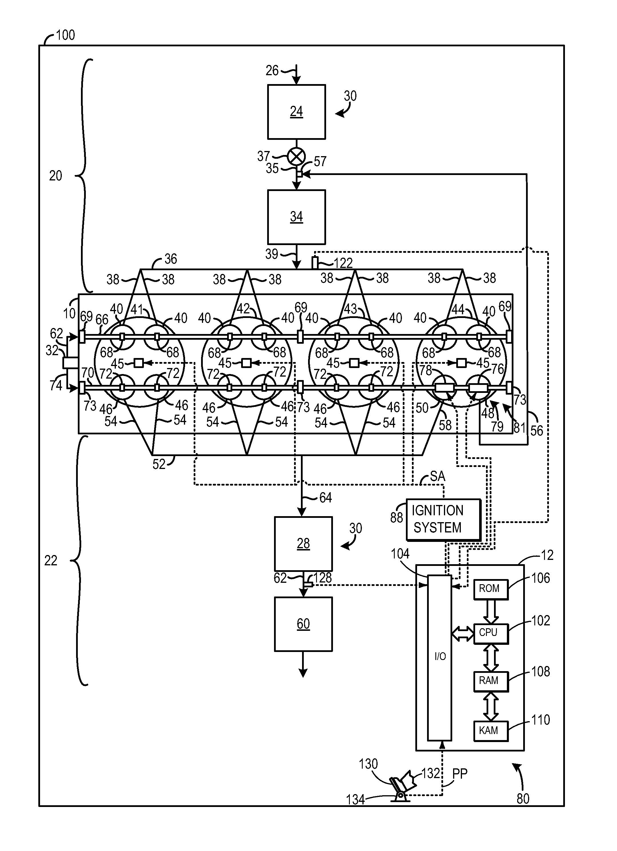
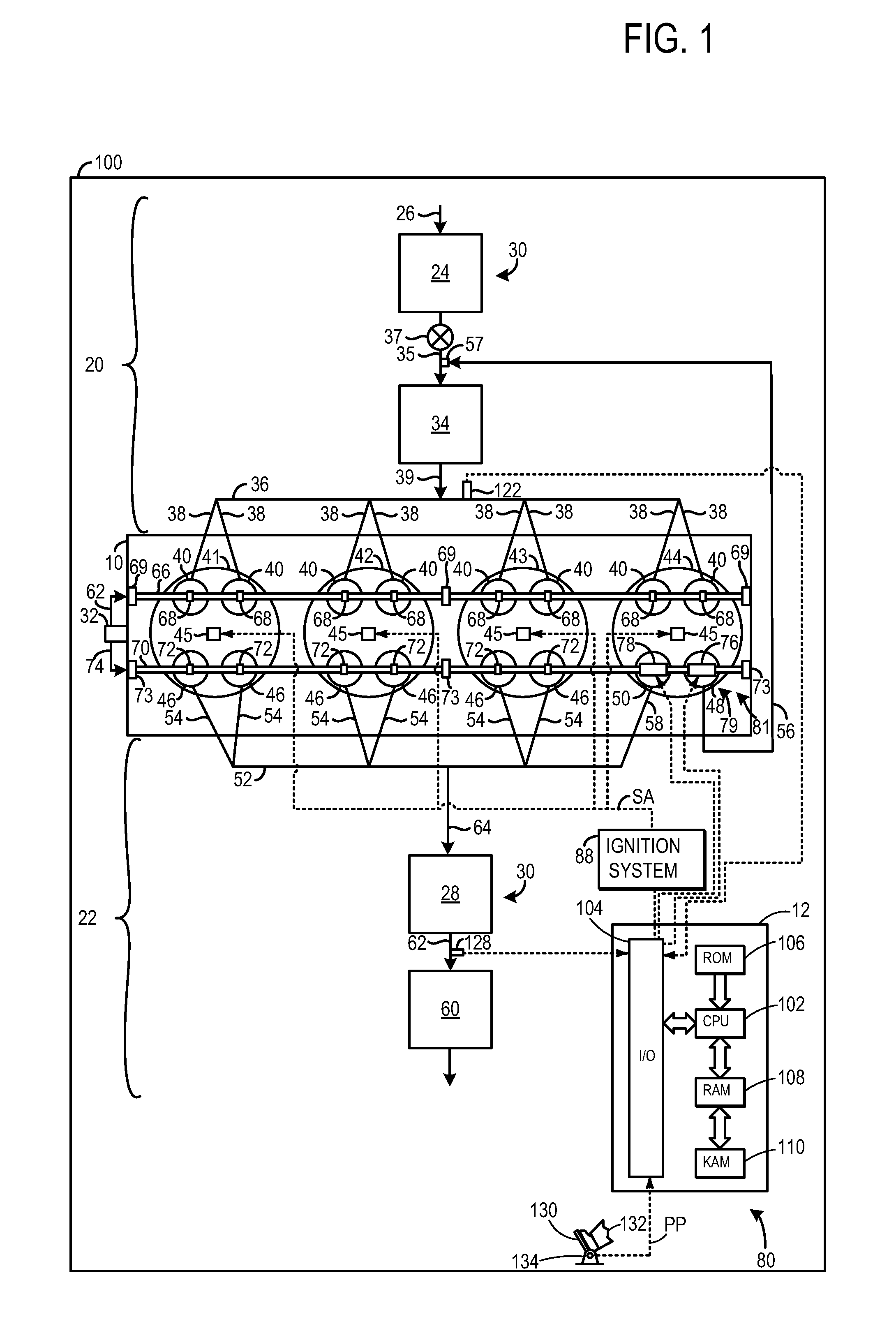
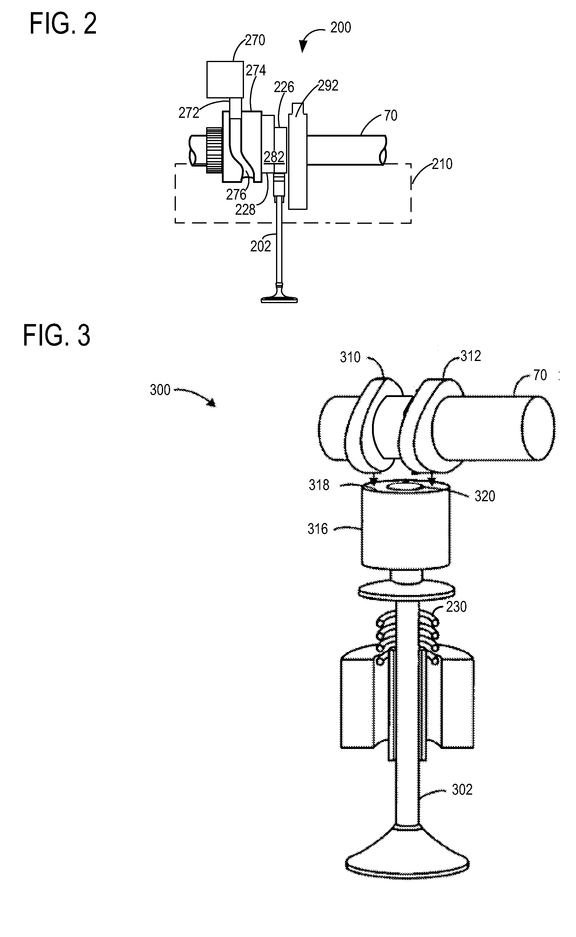
[0016]An engine is described herein. The engine may include a valve adjusting device configured to permit and inhibit exhaust gas flow from a cylinder to an exhaust gas recirculation (EGR) conduit and from the cylinder to the exhaust system. For example, a first exhaust valve in the cylinder (coupled to an EGR passage leading to the engine intake) may be active during some conditions while a second exhaust valve in the cylinder (coupled to the exhaust of other cylinders) may be active during other conditions. In this way, valve activation / deactivation during engine combustion cycles may be used to adjust the flow of exhaust gas to dedicated EGR and exhaust conduits. For example, substantially all of the exhaust gases in the cylinder may flow to either the EGR conduit (and not the exhaust system), or the exhaust system (and not the EGR conduit) under different conditions, thereby utilizing the exhaust gases of that cylinder for improved fuel economy or exhaust aftertreatment light-of...


PUM


Abstract

An engine is provided that includes an exhaust gas recirculation (EGR) conduit in fluidic communication with a first exhaust valve in a cylinder and an intake system, an exhaust conduit in fluidic communication with a second exhaust valve in the cylinder and an emission control device. During operation with the first valve active and the second valve deactivated, a fixed EGR level can be provided. However, during operation with the first valve deactivated and the second valve active, increased engine output can be achieved with reduced EGR without requiring additional exhaust throttling or switching valves.

Description

FIELD[0001]The present disclosure relates to an engine having valve adjustment devices for altering the flow of exhaust gas from a cylinder selectively to each of an exhaust gas recirculation conduit and an exhaust system.BACKGROUND AND SUMMARY[0002]Exhaust gas recirculation (EGR) may be used in engines to decrease emissions (e.g., nitrogen oxide emissions), improve knock tolerances, improve combustion efficiency, and reduce throttling losses. EGR may be employed in engines utilizing compression or spark ignition. EGR system may flow exhaust gas from one or more of the cylinders in the engine to the engine's intake system via an EGR conduit. EGR valves may be disposed in EGR conduits to regulate exhaust gas flow through the conduits.[0003]US 2012 / 0260897 discloses an EGR system having two dedicated EGR cylinders, each cylinder having two exhaust valves configured to flow exhaust gas to an EGR conduit or an exhaust treatment device in the exhaust system based on the configuration of ...

Claims


Application Information

Patent Timeline
Patent Type & Authority Applications(United States)
IPC IPC(8): F02M25/07F02B47/08
CPCF02B47/08F02M25/07Y02T10/121F01L1/143F01L13/0031F01L2013/0052F02D13/0242F02D13/0246F02D13/0257F02D41/0055F02D41/0065F02D41/0255F02D2021/083F02D2041/001F02M26/05F02M26/43Y02T10/12Y02T10/40
Inventor BOYER, BRAD ALANCURTIS, ERIC WARRENKU, KIM HWEMCCONVILLE, GREGORY PATRICKERVIN, JAMES DOUGLASSTYLES, DANIEL JOSEPHULREY, JOSEPH NORMANSHELBY, MICHAEL HOWARD
Owner CMR TECH
Why Eureka
Try Eureka