Modular panel for thermal energy transfer

a module panel and thermal energy technology, applied in the direction of domestic heating details, space heating and ventilation details, sustainable buildings, etc., can solve the problems of limited power output of the panel, very little assembly flexibility, and affecting both the panel itself and the thermal surface, so as to prevent the formation of air pores, increase the durability of the installation, and ensure the mobility

Active Publication Date: 2014-07-17
SANCHEZ ENRIQUE TARRAGA +4
View PDF15 Cites 16 Cited by
  • Summary
  • Abstract
  • Description
  • Claims
  • Application Information

AI Technical Summary

Benefits of technology

[0036]Likewise, in order to compensate for the expansions said hydraulic pipes frequently experience due to their temperature changes, an expansion joint made of an elastic material having the same cross-section as that corresponding to the adjacent panels is arranged at the linking points of the conducting plates of said adjacent panels forming the thermal surface. Furthermore, even though the closure means exert pressure on the hydraulic pipe to assure its contact with the groove, said pipe is not fixed thereto and has certain mobility. The mobility of the pipe and the expansion joints between panels allow absorbing the expansions occurring while the installation is o

Problems solved by technology

Current panels like the one described above have considerable drawbacks affecting both the panel itself and the thermal surface obtained by means thereof, as well as assembly process for assembling said surface, as can be inferred below.
In terms of the panel itself, it has a modularity limited to practically only three or four different sizes which are generally obtained from a standard, large-sized panel, so it offers very little assembly flexibility.
Furthermore, the power output of the panel is limited by the low heat conduction capacity of the plaster.
Finally, the integration of the hydraulic circuit makes the panel more expensive, more complex to manufacture and less manageable, and it does not allow access to said circuit for maintenance purposes without previously having to break the panel itself.
In terms of the surface obtained by means of current panels, particularly the drawbacks affecting the proper operation of the installation and the low exploitation of the available surface of the enclosure should be pointed out.
All this, in addition to the long assembly time it represents resu

Method used


Image

  • Modular panel for thermal energy transfer
  • Modular panel for thermal energy transfer
  • Modular panel for thermal energy transfer

Examples


Embodiment Construction

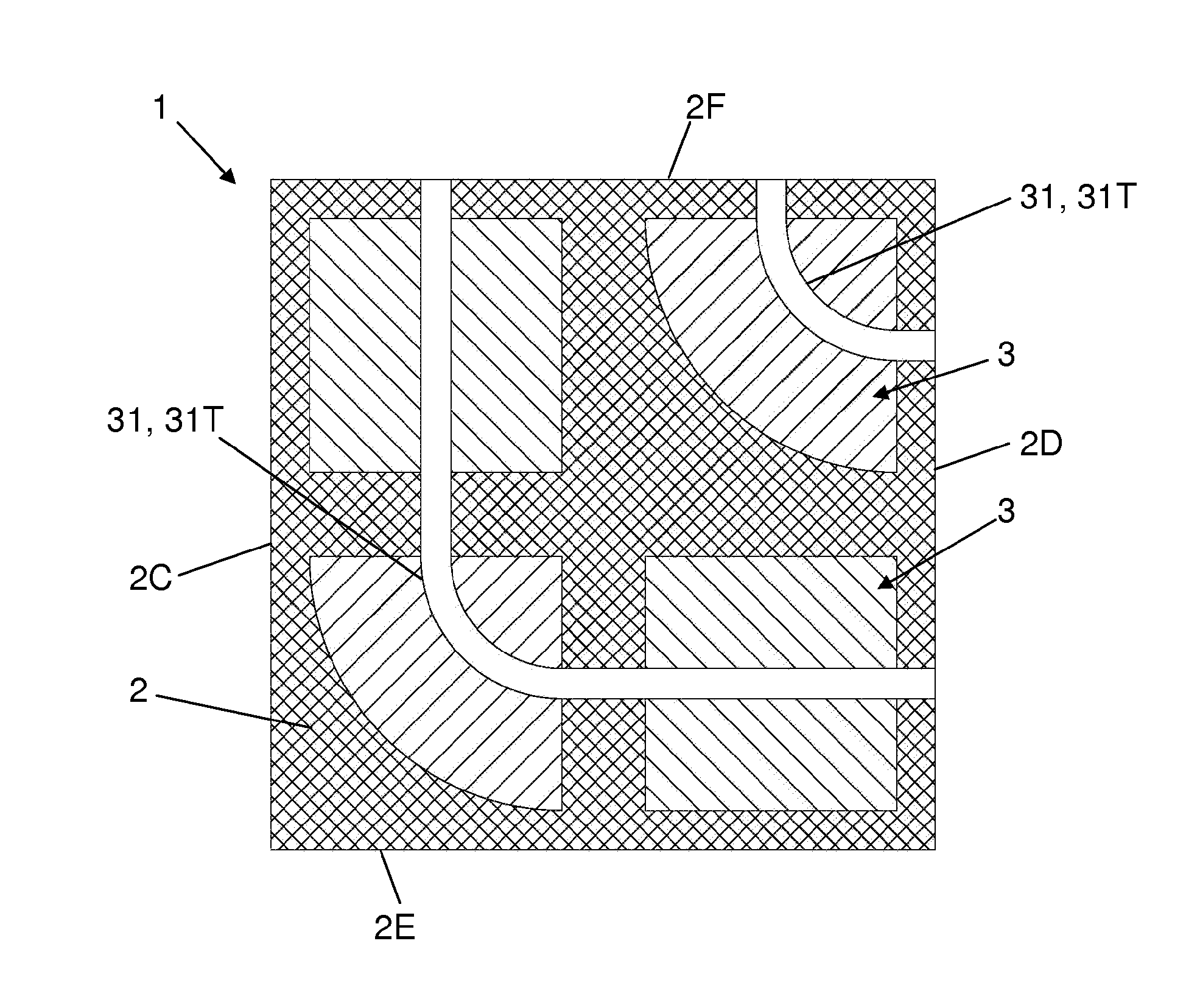
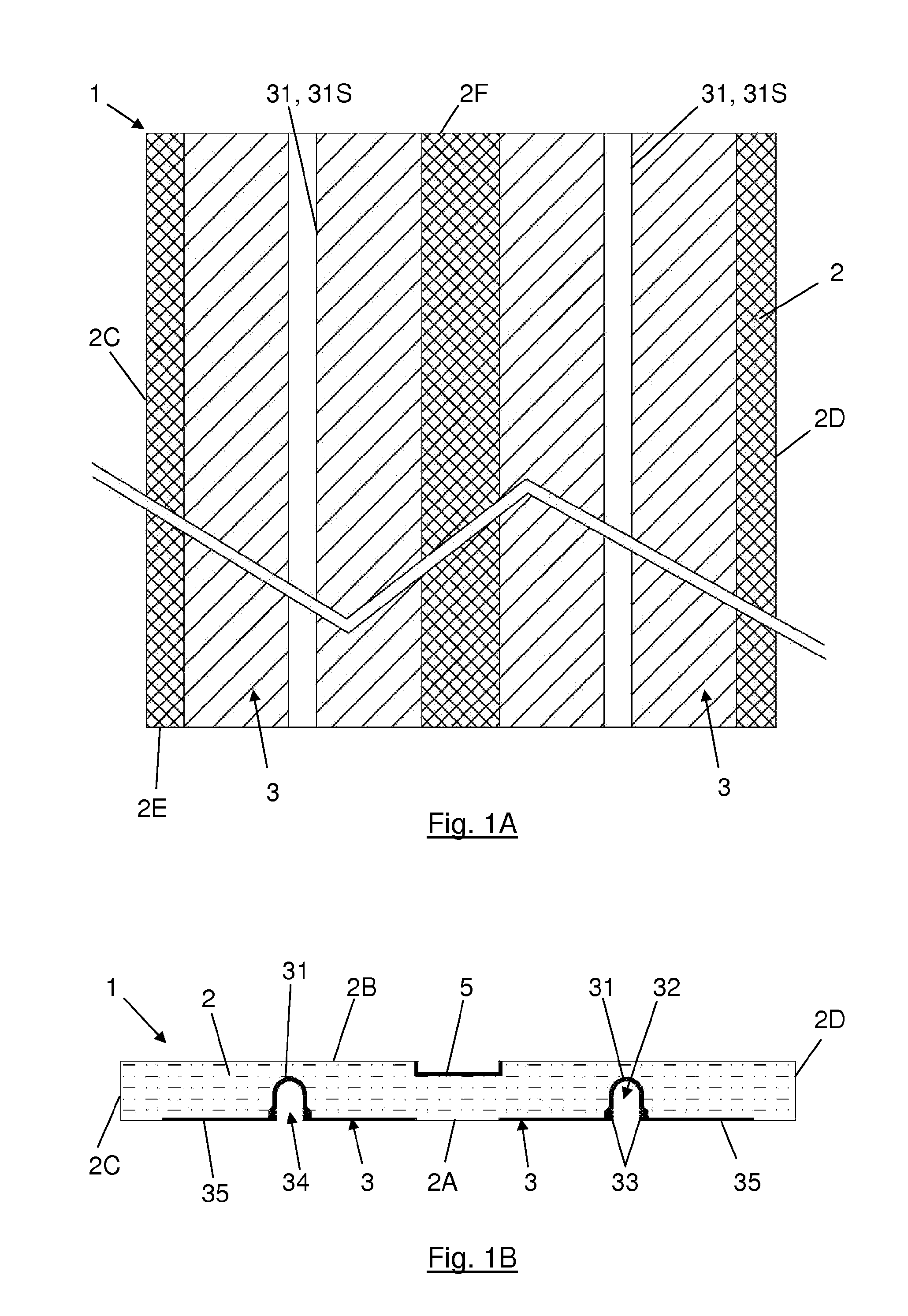
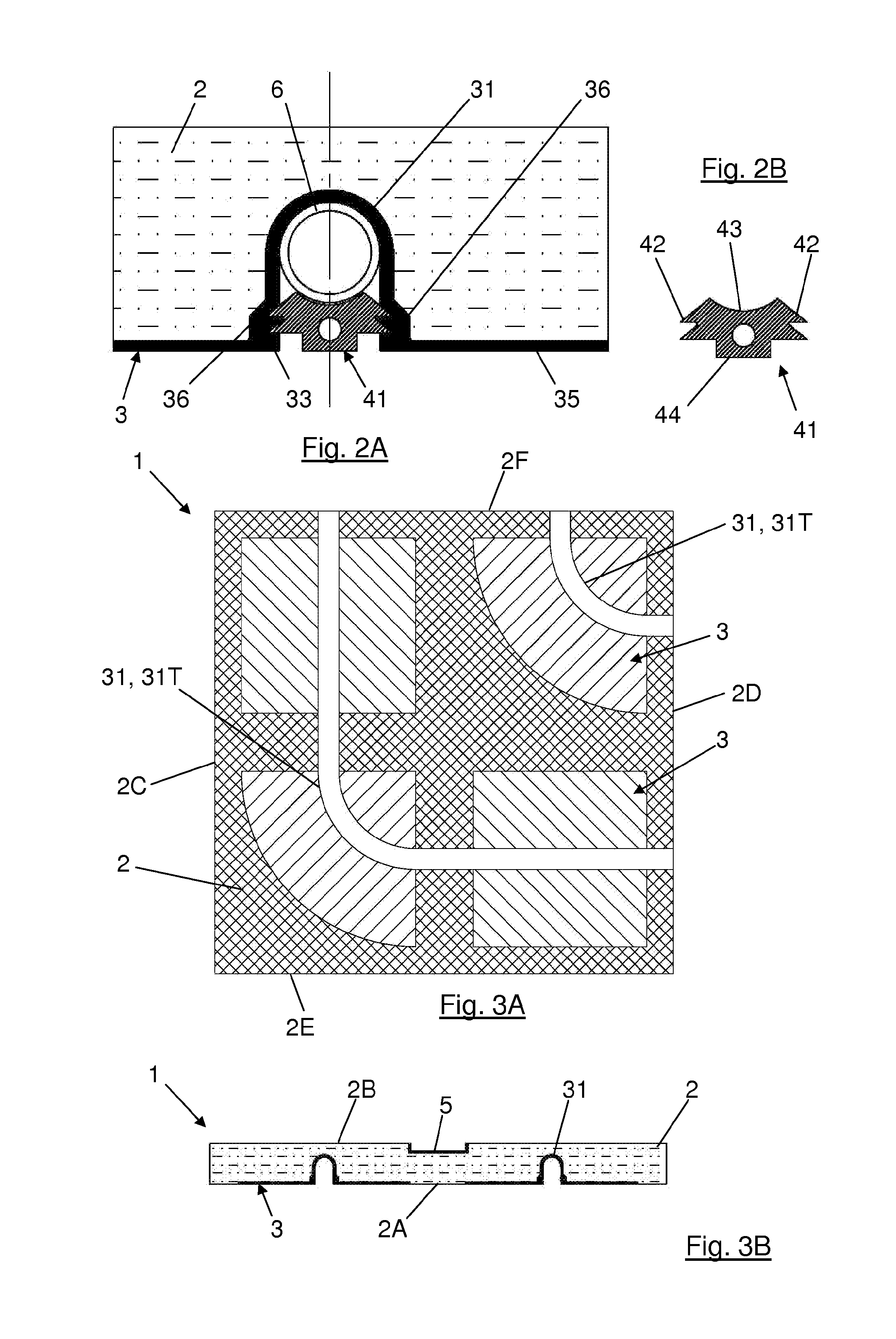
[0013]According to a first object of the present invention a modular panel for thermal energy transfer particularly configured for being used in ceilings and walls is described below.

[0014]Said modular panel comprises a heat-insulating layer preferably having a square or rectangular base, forming a supporting structure demarcated by at least one lower face, an upper face, two side faces and two end faces. The materials which can be used to form the insulation layer are great in number and very diverse, such as for example synthetic polymer foams (such as polyisocyanurate, polyurethane, etc.), mineral wools and natural plant-based insulations, among others.

[0015]In turn, the panel also comprises at least one preferably aluminum conducting plate attached to the lower face of the heat-insulating layer. The conducting plate is likewise formed by:[0016]a groove embedded in the heat-insulating layer defining a longitudinal cavity which is configured to house a hydraulic pipe, said groove ...


PUM

PropertyMeasurementUnit
Angleaaaaaaaaaa
Angleaaaaaaaaaa
Temperatureaaaaaaaaaa

Abstract

The present invention relates to a modular panel for thermal energy transfer particularly configured for being used in ceilings and walls, comprising a heat-insulating layer (2) forming a supporting structure demarcated by a lower face (2A), an upper face (2B), two side faces (2C, 2D) and two end faces (2E, 2F). Said panel (1) comprises at least one conducting plate (3) attached to the lower face (2A). Said conducting plate (3) is formed by a groove (31) embedded in the heat-insulating layer (2), defining a longitudinal cavity (32) which is configured to house a hydraulic pipe (6), and defining a longitudinal opening (34) which allows inserting the hydraulic pipe (6); a transfer plate (35) extending on the lower face (2A) and closure means (4) configured to seal the longitudinal opening (34) and press the hydraulic pipe (6) against the groove (31).

Description

OBJECT OF THE INVENTION[0001]The present invention relates to a modular panel for thermal energy transfer to a thermal surface for the thermal conditioning of an enclosure obtained by means of a plurality of said modular panels and to an assembly process thereof.[0002]The present invention has especially been designed for thermal conditioning installations in buildings of the type using modular panels in ceilings and / or walls.[0003]The present invention allows improving the energy efficiency of current installations, minimizes the occurrence of breakdowns while the installation is operating because it does not require intermediate connections of the hydraulic circuit between panels, maximizes the exploitation of the available surface of the enclosure to be conditioned and facilitates assembly tasks.BACKGROUND OF THE INVENTION[0004]Thermal conditioning installations in buildings have three clearly distinguished functional parts. The first one corresponds to the thermal energy generat...

Claims


Application Information

Patent Timeline
IPC IPC(8): E04C2/52E04B5/48F24D3/14
CPCE04C2/525E04B5/48F24D3/14F24D3/142F24F5/0092F24F5/0089F24D3/148Y10T29/49629Y10T29/49634Y02B30/00
Inventor TARRAGA SANCHEZ, ENRIQUEJORDAN FERNANDEZ, LUIS
Owner SANCHEZ ENRIQUE TARRAGA
Why Eureka
Try Eureka