
Microphone Environmental Protection Device

Active Publication Date: 2014-07-17
RED TAIL HAWK CORP
View PDF17 Cites 56 Cited by
  • Summary
  • Abstract
  • Description
  • Claims
  • Application Information

AI Technical Summary

Benefits of technology

The present invention is a device that protects a microphone from damage caused by rain, wind, dirt, salt crystals, and objects. It does this by using a chamber with a perforated barrier to prevent such elements from contacting the microphone surface. The device also prevents direct impact from small particles like sand and dust, water, and wind, which can cause damage to the microphone. This results in improved protection against damage. Additionally, the invention may also improve the signal-to-noise ratio of the microphone by providing acoustic amplification. The invention can be attached to a noise-defending headset ear cup, where it senses the sound outside of the ear cup and provides amplification and / or attenuation of the sound for the user's benefit. The invention may also be incorporated in manikins or other mechanical structures used to mimic the diffraction of sound around the human head.

Problems solved by technology

However, there are significant problems with using porous materials such as foam.
Foam and other similar porous materials become clogged with water when submerged or subject to rain.
High frequency sounds are attenuated; therefore, the microphone signal no longer provides an accurate representation of sound in the ambient acoustic environment.
Microphones have inherent noise associated with them called “self-noise.” Even in a perfectly quiet ambient environment, microphones will generate electrical noise at their output.
This noise is due to the self-noise of electrical amplifier components, such as the “Johnson noise” of resistances and “flicker noise” of transistors.
The acoustical and mechanical damping of a microphone diaphragm also contributes to the self-noise of a microphone.

Method used


Image

  • Microphone Environmental Protection Device
  • Microphone Environmental Protection Device
  • Microphone Environmental Protection Device

Examples


Embodiment Construction

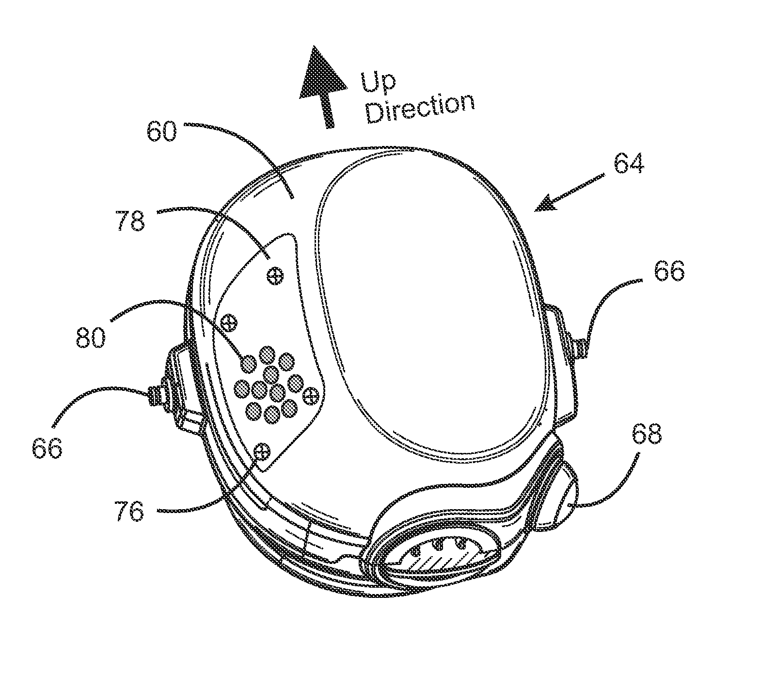
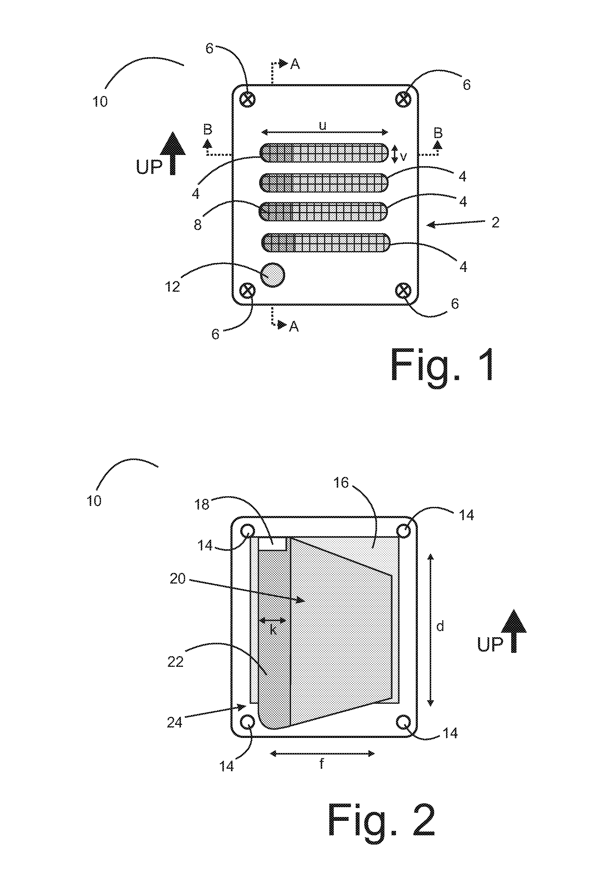
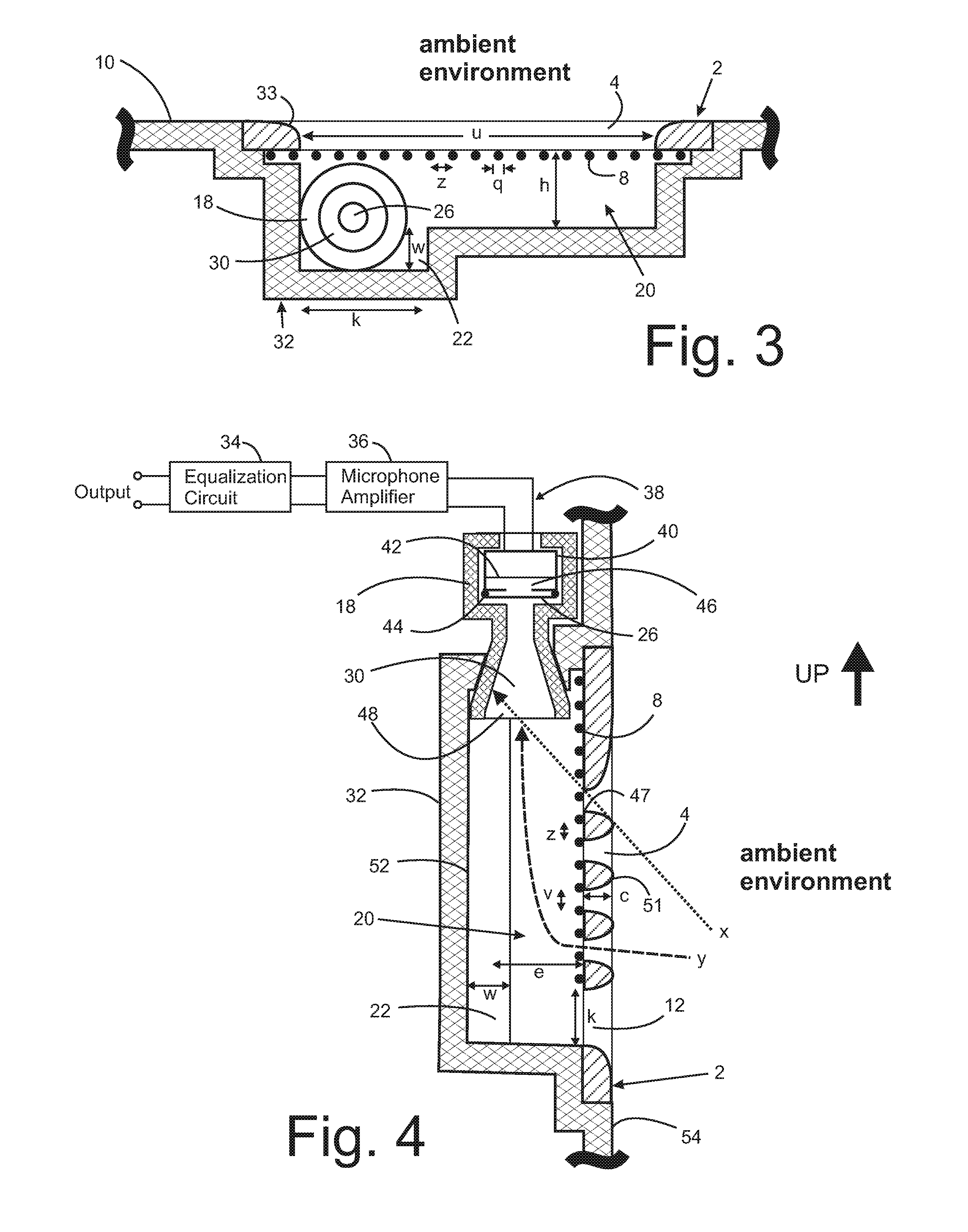
[0023]An embodiment of the invention is a device for protecting microphones against environmental damage which incorporates a special perforated barrier on the outer surface of a chamber, which provides a line of sight from outside the chamber volume to inside the chamber volume. The cross-sectional area of the perforations are large enough that water can easily pass through the barrier and the barrier is self-cleaned with rain or can be cleaned deliberately with a spray bottle. An outer layer of the barrier can be made of a solid rigid material, such as plastic or metal, with slotted perforations backed by an inner layer of metal mesh material.

[0024]A drainage path can be provided for water and debris that accumulate in the chamber volume. The water drain may be a path back through the perforated barrier, or a separated dedicated drain path can be provided. This allows the device to be self-cleaning during rain and easily to clean using a spray bottle.

[0025]The barrier in this embo...


PUM


Abstract

A device for protecting a microphone sensing surface, such as a diaphragm, from the detrimental effects of the ambient environment. The device incorporates a perforated surface to protect the microphone and in conjunction with a chamber volume creates an acoustic resonance in the 1 kHz to 20 kHz spectrum, which improves the microphone signal-to-noise ratio performance. The microphone is acoustically coupled to the chamber volume for sensing pressure of the ambient environment. There is no line of sight to the microphone sensing surface from the ambient environment, so that rain, wind and sand have no direct path to the microphone sensing surface. The perforations of the outer surface are small to prevent objects from contacting the microphone sensing surface via a direct path. Water drains from the chamber volume and does not become trapped if an embodiment of the invention is temporarily submerged so that the microphone returns to normal operation quickly.

Description

REFERENCE TO RELATED APPLICATIONS[0001]This application claims one or more inventions which were disclosed in Provisional Application No. 61 / 751,527, filed Jan. 11, 2013, entitled “Microphone Environmental Protection Device”. The benefit under 35 USC §119(e) of the United States provisional application is hereby claimed, and the aforementioned application is hereby incorporated herein by reference.BACKGROUND OF THE INVENTION[0002]1. Field of the Invention[0003]This invention relates to devices used to protect microphones from the ambient environment.[0004]2. Description of Related Art[0005]Microphone screens typically incorporate porous materials, such as foamed material and metal mesh, to protect the microphone sensing surface, such as a diaphragm from being damaged by objects, such as fingers, and to prevent wind noise. Inventions such as those described in U.S. Pat. No. 7,496,208, U.S. Pat. No. 2,520,706 and U.S. Pat. No. 3,154,171 illustrate such examples.[0006]However, there ar...

Claims


Application Information

Patent Timeline
IPC IPC(8): H04R1/08
CPCH04R1/086H04R2410/07H04B1/385Y10S2/909Y10S2/906H04R1/1075
Inventor PARKINS, JOHN W.
Owner RED TAIL HAWK CORP
Features
  • Generate Ideas
  • Intellectual Property
  • Life Sciences
  • Materials
  • Tech Scout
  • Unparalleled Data Quality
  • Higher Quality Content
  • 60% Fewer Hallucinations
Learn More