System and method for network synchronization and frequency dissemination

Active Publication Date: 2014-07-17
STICHTING VU
View PDF13 Cites 29 Cited by
  • Summary
  • Abstract
  • Description
  • Claims
  • Application Information

AI Technical Summary

Benefits of technology

The patent aims to provide accurate timing in a packet-based telecommunications network, particularly for mobile devices. The method involves transmitting timing data and a response back and forth between nodes using a single optical fiber. This helps to improve synchronization accuracy. The latency of the signal transfer can be determined by measuring the delay between sending and receiving the timing signal. The method also suggests using different wavelengths for the timing data and response to prevent cross-talk between data due to scattering. Overall, this patent proposes a way to enhance the accuracy of timing in optical communication networks.

Problems solved by technology

Packet switched networks do not use such a fixed framing architecture, and therefore do not have a natural synchronized timing distribution.
As the vast majority of mobile backhaul networks are upgraded to (Carrier) Ethernet, the base stations become unsynchronized.
However, this approach is expensive and can easily be tampered with.
However, Synchronous Ethernet is not capable of providing accurate time and phase information as is needed in packet networks.
However, to use PTP, additional hardware and boundary clocks are needed for regeneration and jitter compensation of timing signals in extensive networks.
Furthermore, with PTP only limited synchronization accuracy can be achieved, typically of the order of 1 microsecond.

Method used


Image

  • System and method for network synchronization and frequency dissemination
  • System and method for network synchronization and frequency dissemination
  • System and method for network synchronization and frequency dissemination

Examples


Embodiment Construction

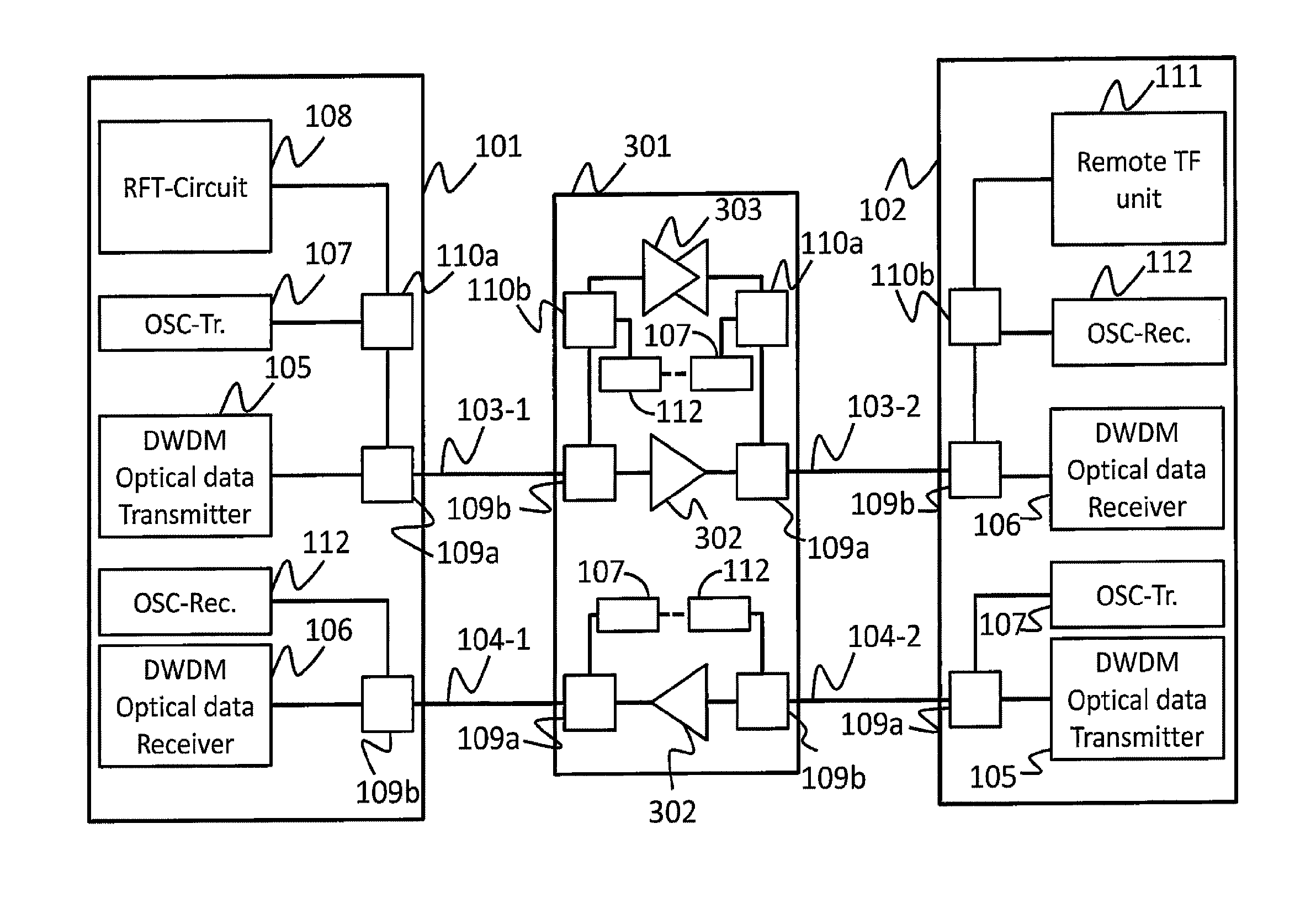
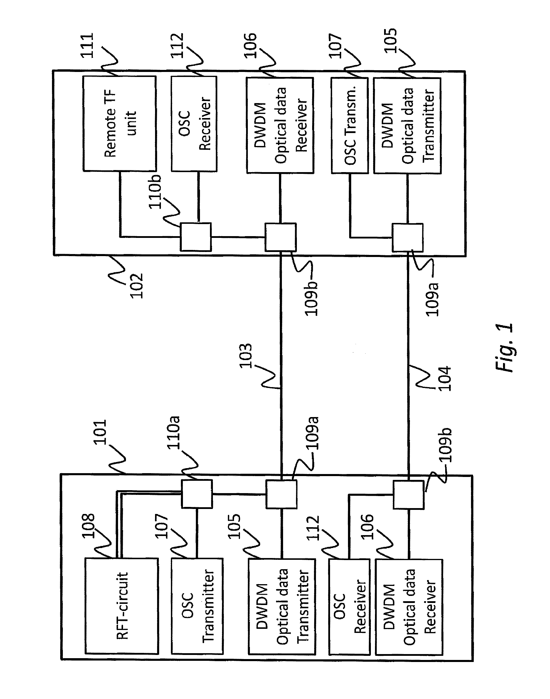
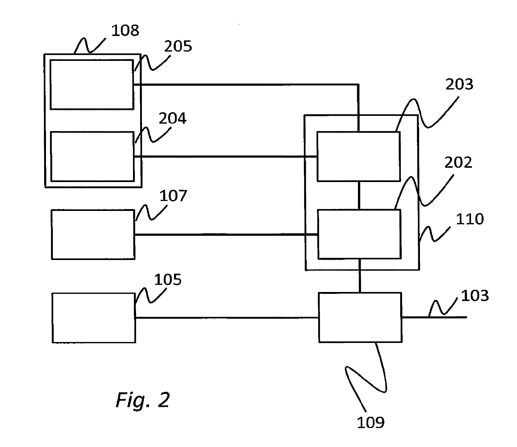
[0018]An embodiment of the invention provides an optical filter for use in a transmitter in a Dense Wavelength Division Multiplexed, DWDM, transmission system, the optical filter comprising: a first port for communicative coupling to a reference frequency and timing circuit; a second port for communicative coupling to an optical supervisory channel, OSC, transmitter unit; and a third port for communicative coupling to a further optical filter arranged for enabling transmission of DWDM optical data over an optical fiber; wherein the optical filter is arranged for: receiving a reference frequency and timing signal via the first port; receiving an OSC signal via the second port; combining the frequency and timing reference signal and the OSC signal so as to form a combined signal; transmitting the combined signal towards the further optical filter via the third port. The reference frequency and timing signal that is combined with the OSC-signal enables a receiver that receives the comb...


PUM


Abstract

Distribution of reference frequency and timing information in a network involves determining latency between a first and second node from time delay between transmission of a reference frequency and timing signal and reception of an optical return timing signal in response. In a network with pairs of first and second optical fibers in optical fiber connections between network nodes, for transmission of optical data signals separately in mutually opposite directions between the network nodes respectively, provisions are made to transmit the reference frequency and timing signal and the resulting optical return signal via the same fiber, one in the same direction as the unidirectional data signal over that fiber and the other upstream. Repeaters between the nodes may be modified to pass such signals upstream and downstream. In an embodiment wherein the network provides for an optical supervisory channel, the optical filters for combining the optical supervisory channel signal with the unidirectional data signal and separating the optical supervisory channel signal from the unidirectional data signal are used to combine and separate the reference frequency and timing signal and to pass the optical return timing signal. For this purpose, further optical filters may be added outside the main optical data channel to combine and separate the reference frequency and timing signal and the optical supervisory channel and to pass the optical return signal back to the filter that separates the optical supervisory channel signal from the data signal.

Description

FIELD OF THE INVENTION[0001]The present invention relates to a system and method for time and frequency synchronization in communication networks, in particular duplex optical fiber networks such as DWDM (Dense Wavelength Division Multiplexed) transmission systems.BACKGROUND ART[0002]The international telecommunication needs for data transmission are rapidly growing in recent years, the main drivers being video, supercomputing applications and data traffic via mobile communications. Under these conditions, terrestrial optical fiber transmission systems, such as DWDM (Dense Wavelength Division Multiplexed) transmission systems have been developed to meet the increasing demands for more cost-effective, bandwidth-rich telecommunication service. Furthermore, in order to accommodate the different types of traffic on the network (e.g. voice, data, video) and to increase the utilization of the available bandwidth in the network, network architectures migrate from circuit switched networks ...

Claims


Application Information

Patent Timeline
IPC IPC(8): H04L7/00H04J14/02
CPCH04J14/02H04L7/0075H04J3/0682H04J14/0272H04J14/0275
Inventor NUIJTS, ROELAND JOHANNUS MARIE WILHELMKOELEMEIJ, JEROEN CORNELIS JEAN
Owner STICHTING VU
Why Eureka
Try Eureka