
Vibrational photoacoustic tomography using raman laser

Active Publication Date: 2014-07-17
PURDUE RES FOUND INC
View PDF4 Cites 10 Cited by
  • Summary
  • Abstract
  • Description
  • Claims
  • Application Information

AI Technical Summary

Benefits of technology

This patent encourages advancements in imaging technology that can improve the quality of images captured using VPAT. These improvements include higher pulse energy, which allows for deeper tissue imaging, and excitation at wavelengths that match natural resonances. These advancements have the potential to make VPAT imaging more effective and reliable for a range of applications.

Problems solved by technology

However, vibrational imaging of deep tissues has been a formidable challenge due to tissue absorption and scattering of both incident photons and generated signals.
For example, though coherent Raman scattering microscopy has allowed fast vibrational imaging, its penetration depth is limited to ˜100 μm because the signal is generated by ballistic photons under a tight focusing condition.
However, effective vibrational photoacoustic tomography (VPAT) has not yet been demonstrated, partly due to the unavailability of a laser source having sufficient energy for diffused photon excitation of harmonic vibration.

Method used


Image

  • Vibrational photoacoustic tomography using raman laser
  • Vibrational photoacoustic tomography using raman laser
  • Vibrational photoacoustic tomography using raman laser

Examples


Embodiment Construction

[0030]Throughout this description, some aspects are described in terms that would ordinarily be implemented as software programs. Those skilled in the art will readily recognize that the equivalent of such software can also be constructed in hardware, firmware, or micro-code. Because data-manipulation algorithms and systems are well known, the present description is directed in particular to algorithms and systems forming part of, or cooperating more directly with, systems and methods described herein. Other aspects of such algorithms and systems, and hardware or software for producing and otherwise processing signals or data involved therewith, not specifically shown or described herein, are selected from such systems, algorithms, components, and elements known in the art. Given the systems and methods as described herein, software not specifically shown, suggested, or described herein that is useful for implementation of any aspect is conventional and within the ordinary skill in ...


PUM


Abstract

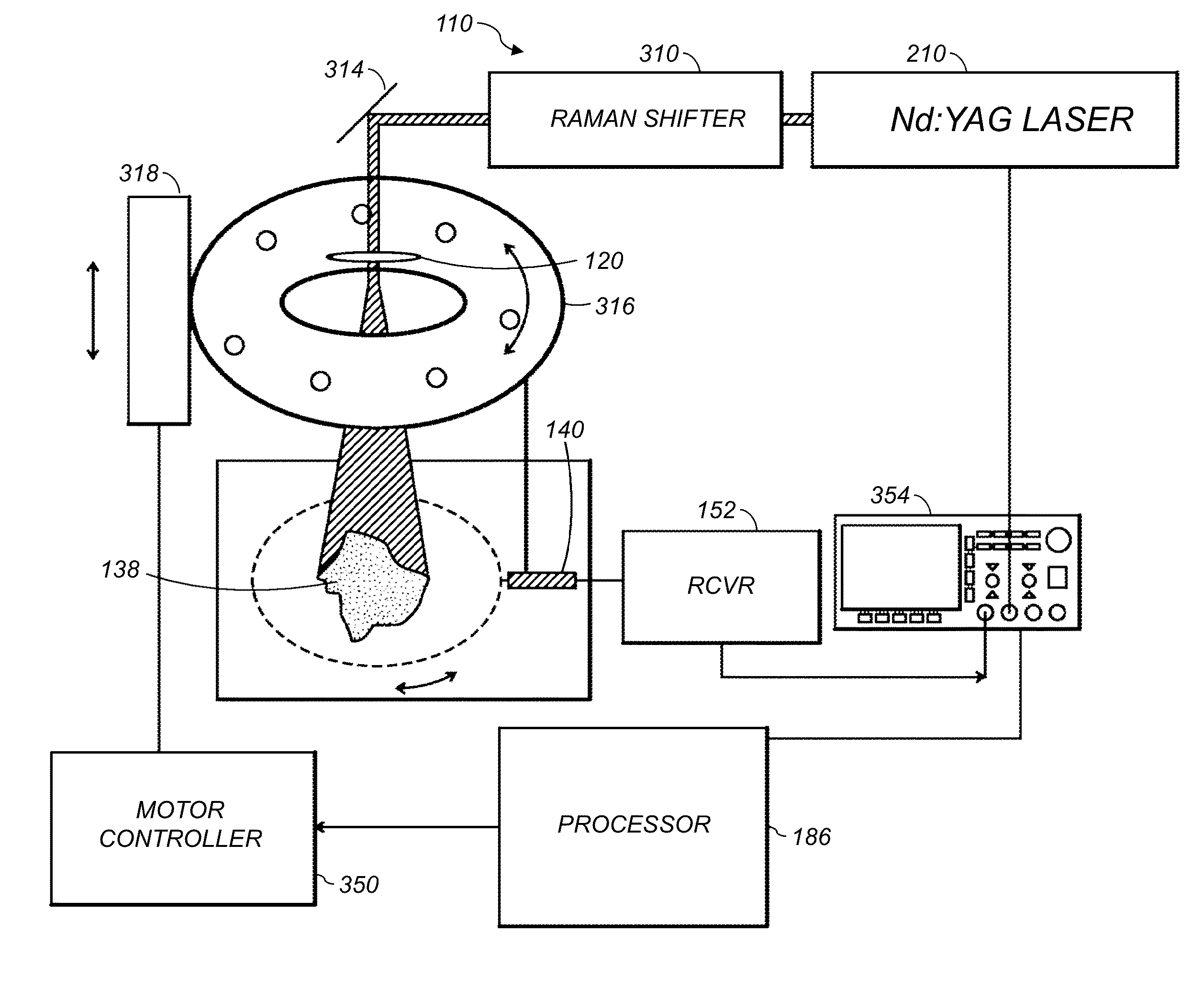
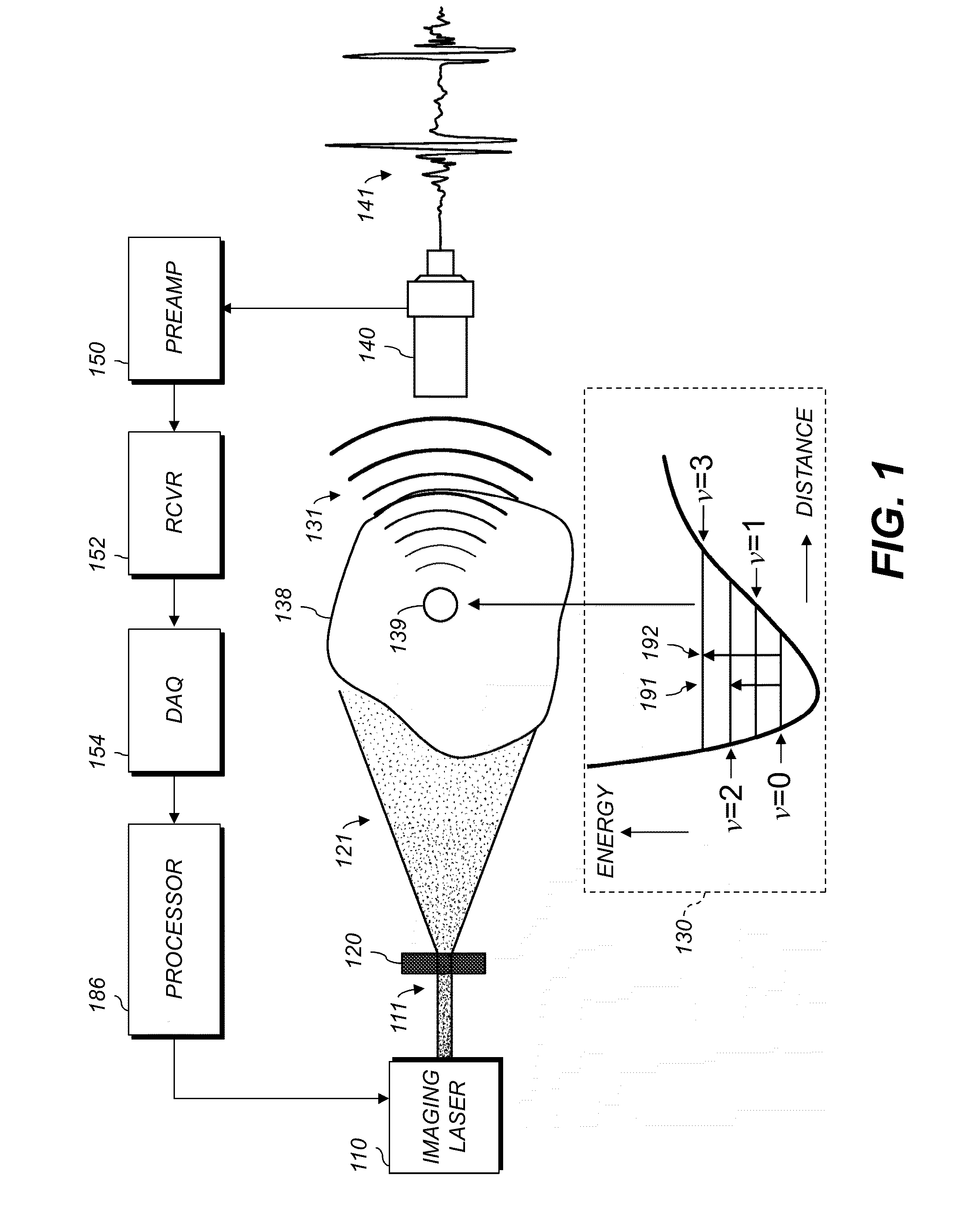
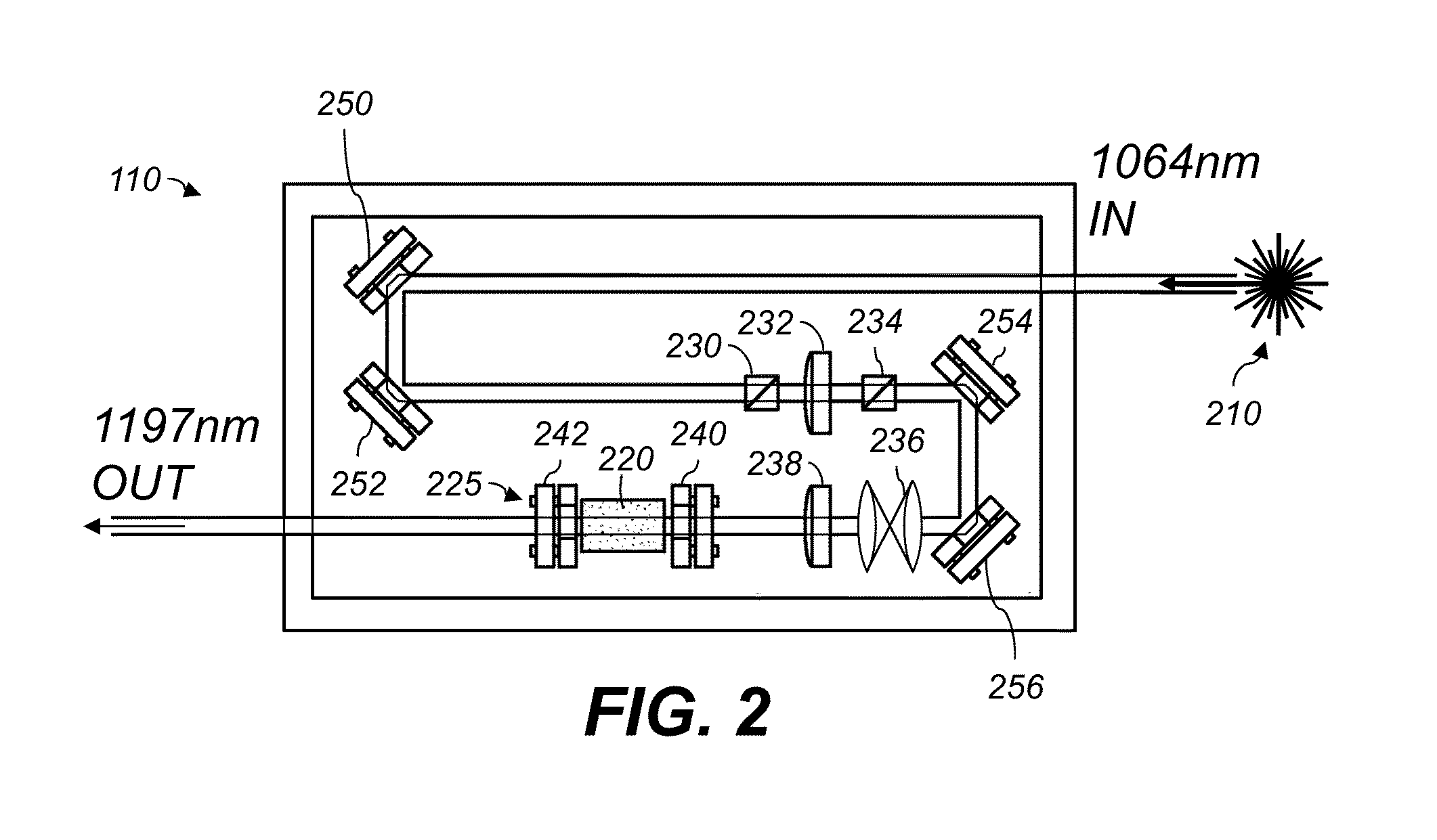
A method of noninvasively imaging tissue within a body includes irradiating the tissue using an imaging laser including a Raman-based laser tuner, the radiation including a plurality of laser pulses, each having energy greater than 100 mJ; receiving an acoustic signal generated by vibrational energy in the tissue, wherein the vibrational energy is a result of selective overtone excitation of molecules in the tissue by the radiation; and automatically converting the acoustic signal to an image representative of the tissue using a processor. An imaging system includes an imaging laser configured to irradiate tissue with a plurality of laser pulses using a Raman-based laser tuner. An ultrasonic transducer receives an acoustic signal generated by vibrational energy in the tissue due to overtone excitation by the radiation. A processor is configured to automatically produce an image representative of the tissue using the received acoustic signal.

Description

CROSS-REFERENCE TO RELATED APPLICATIONS[0001]This nonprovisional application claims the benefit of U.S. Provisional Application Ser. No. 61 / 753,007, filed Jan. 16, 2013 and of U.S. Provisional Application Ser. No. 61 / 872,414, filed Aug. 30, 2013 and is a continuation-in-part of International Application Ser. No. PCT / US2013 / 023095, filed Jan. 25, 2013 which claims the benefit of U.S. Provisional Application Ser. No. 61 / 753,007, filed Jan. 16, 2013 and of U.S. Provisional Application Ser. No. 61 / 592,819, filed Jan. 31, 2012 the entirety of each of which is incorporated herein by reference.STATEMENT OF FEDERALLY SPONSORED RESEARCH OR DEVELOPMENT[0002]This invention was made with Government support under Contract No. EB015901 awarded by the National Institutes of Health. The government has certain rights in the invention.TECHNICAL FIELD[0003]The present application relates to vibrational photoacoustic tomography, and more specifically to imaging tissue using vibrational photoacoustic to...

Claims


Application Information

Patent Timeline
IPC IPC(8): A61B5/00
CPCA61B5/0095
Inventor CHENG, JI-XIN
Owner PURDUE RES FOUND INC
Learn More