Optical sensor

a technology of optical sensors and optical fibers, applied in the field of optical sensors, can solve the problems of lenses and fibres not experiencing the full temperature in a combustion zone, and achieve the effect of simple manufacturing

Active Publication Date: 2014-07-24
OXSENSIS
View PDF2 Cites 12 Cited by
  • Summary
  • Abstract
  • Description
  • Claims
  • Application Information

AI Technical Summary

Benefits of technology

[0033]The present invention further provides an optical sensor comprising an optical assembly comprising a spacer and an optical waveguide, the spacer having a first end face which in use is subjected to a first temperature, and a second end face to which is coupled an optical waveguide, said optical waveguide configured for use up to a second temperature lower than the first temperature, the spacer providing a thermal gradient between the first end face and second end face when in use, wherein the optical waveguide is arranged to collect radiation from the environment of the first end face of the spacer which has been transmitted through the spacer to the second end face. The collection optics optically couple the radiation from the spacer into the waveguide. This allows remote detection of radiation collected

Problems solved by technology

The thermal gradient results in the lens and fibre not

Method used


Image

  • Optical sensor
  • Optical sensor
  • Optical sensor

Examples


Embodiment Construction

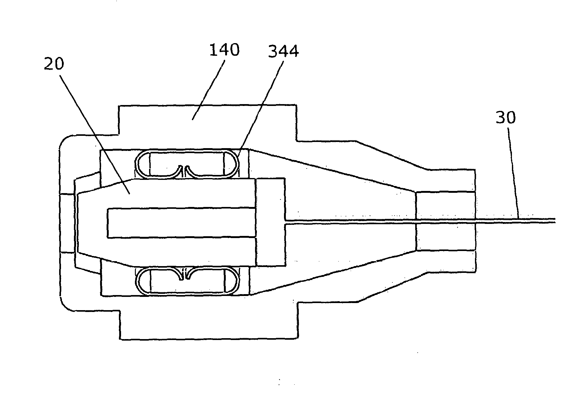
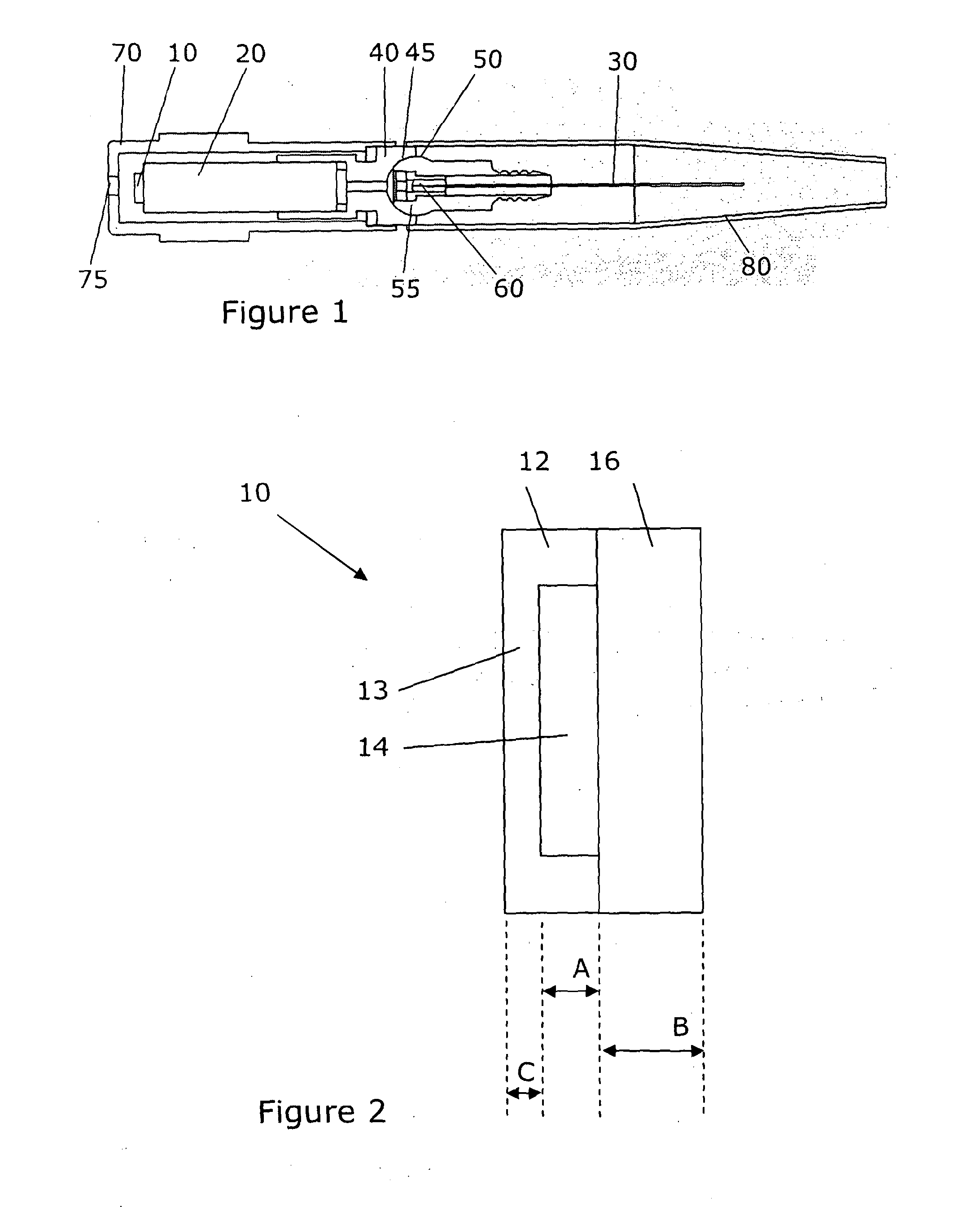
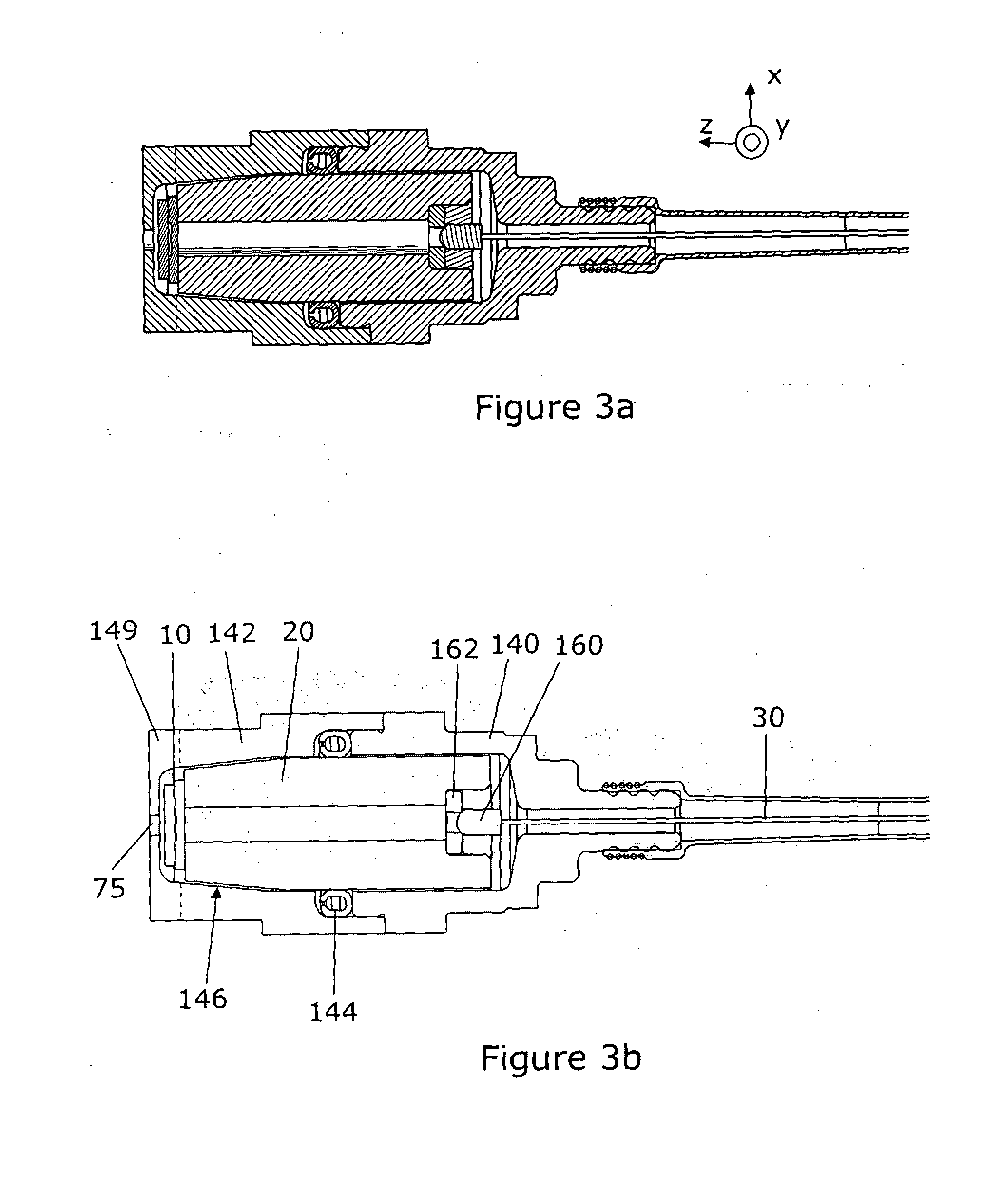
[0060]FIGS. 3a and 3b show a sensor according to an embodiment of the present invention. FIG. 3a shows the component parts as solid forms, whereas FIG. 3b shows the outline of the parts. FIGS. 3a and 3b are views of a cross-section through the central axis of the sensor. FIG. 5 is a flow chart showing the steps required to assemble the sensor.

[0061]The sensor of FIGS. 3a and 3b comprises a sensor element 10 comprised of two pieces of sapphire bonded together to form a “pill” structure. One of the pieces has a recess in the surface such that when bonded the other piece the pill has an enclosed cavity. The fabrication of the sensor element is indicated as step 210 in FIG. 5. The sensor element may be such as described above in reference to FIGS. 1 and 2. At step 220 the sensor element 10 is bonded to the front end of spacer 20 which as in FIGS. 1 and 2 may be a rod or tube, but is shown in FIGS. 3a and 3b as a tube. The spacer and sensor element are preferably the same material and th...


PUM

PropertyMeasurementUnit
Temperatureaaaaaaaaaa
Lengthaaaaaaaaaa
Thicknessaaaaaaaaaa

Abstract

An optical sensor is disclosed for measuring pressure and/or temperature. The optical sensor is adapted for use in high temperature environments, such as gas turbines and other engines. The optical sensor comprises an optical assembly having a sensor element, a spacer and a lens arranged along the optical axis. The sensor element is spaced from the lens by the spacer. An optical fibre is coupled to the optical assembly for illuminating the sensor element. The optical assembly is resiliently mounted in a housing such that the optical assembly is insulated from shock to the housing. There is also disclosed a method of assembling the optical sensor.

Description

TECHNICAL FIELD[0001]The present invention relates to an optical sensor and more specifically to an optical sensor for measuring pressure and / or temperature. The optical sensor is adapted for use in high temperature environments, such as gas turbines and other engines.BACKGROUND ART[0002]WO 2009 / 077727 describes an optical sensor for monitoring environmental parameters such as temperature and / or pressure in extreme environments. For example, the sensor is adapted for use at the high temperatures inside gas turbines. The sensor comprises a sensor element which includes an enclosed cavity arranged as a Fabry-Perot cavity, and an optical fibre. Conventional silica optical fibres cannot withstand temperatures above 600° C. whereas the temperature inside gas turbines exceeds this and may be up to 1000° C. Indeed conventional materials for the sensor element, such as silicon, are not able to withstand such extreme temperatures.[0003]The device described in WO 2009 / 077727 addresses these p...

Claims


Application Information

Patent Timeline
IPC IPC(8): G01J1/04G01K11/32G01L11/02
CPCG01J1/0425G01K11/32G01L11/025G01L9/0079G01L19/04G01D5/35312G01K11/3206Y10T156/10G01D5/30G01L11/02G01D5/268G01D11/245G02B6/32G02B6/4239G02B6/424
Inventor HARPIN, ARNOLD PETER ROSCOEFASHAM, STEPHEN JAMESTYLER, STEPHEN GEOFFREY
Owner OXSENSIS
Why Eureka
Try Eureka