Integrity Monitor for Reference Cavity of Capacitance Diaphragm Gauge

a technology of capacitance diaphragm and reference cavity, which is applied in the direction of vacuum gauges using ionisation effects, instruments, and fluid pressure measurement using capacitance variation, etc., can solve the problems of affecting the accuracy of cdg measurement, affecting the integrity of reference vacuum cavity, and affecting the accuracy of cdg

Active Publication Date: 2014-07-24
SUMITOMO SHI CRYOGENICS OF AMERICA
View PDF8 Cites 9 Cited by
  • Summary
  • Abstract
  • Description
  • Claims
  • Application Information

AI Technical Summary

Benefits of technology

[0012]A need exists for an apparatus and a method for detecting an increase in the pressure within the reference vacuum cavity of a CDG. The system disclosed and claimed herein is responsive to the need.
[0013]A system and method detect the presence of an unacceptable quantity of gas molecules in the reference vacuum cavity of a capacitance diaphragm gauge (CDG). An independent pressure transducer has an active portion exposed to the reference vacuum cavity. The transducer includes a ring anode, a cylindrical inner wall surface that forms at least one cathode, and a magnet positioned with respect to the ring anode such that the magnetic flux of the magnet is generally aligned with the central axis of the ring anode. A high voltage source applies a voltage between the ring anode and the cathode. A current sensor senses a magnitude of any current flowing between the ring anode and the cathode via ionized gas molecules. A monitoring unit monitors the magnitude of the current sensed by the current sensor and activates an alarm when the magnitude of the current exceeds an acceptable magnitude.
[0014]An aspect in accordance with embodiments disclosed herein is a method for detecting the presence of an unacceptable quantity of gas molecules in the reference vacuum cavity of a capacitance diaphragm gauge (CDG). The method comprises inserting an independent pressure transducer into the reference vacuum cavity of the CDG, wherein the independent pressure transducer comprises a ring anode, at least one cathode and a magnet. The magnet is positioned to generate a magnetic flux along a central axis of the ring anode. A high voltage is applied between the anode and the cathode to generate an electrical field to ionize gas molecules proximate to the anode and the cathode. The magnitude of a current flowing between the anode and the cathode via the ionized gas molecules is measured. The method

Problems solved by technology

The accuracy of the measurement of pressure by a CDG can be negatively impacted by several factors, one of which is the integrity of the sealed reference vacuum cavity.
Although the reference vacuum cavity of the CDG is sealed, gas molecules may occur within the reference vacuum cavity and degrade the integrity of the reference vacuum cavity after the cavity is sealed.
Common sources of gas molecules include, for example, outgassing from the internal surfaces of the reference cavity, leaks that may occur because of improper manufacturing techniques, diaphragm failure, and pinhole leaks in the diaphragm.
In such circumstances, the CDG exhibits a negative zero shift which adversely impacts the accuracy of the CDG.
The adverse effect on the accuracy of the CDG is

Method used


Image

  • Integrity Monitor for Reference Cavity of Capacitance Diaphragm Gauge
  • Integrity Monitor for Reference Cavity of Capacitance Diaphragm Gauge
  • Integrity Monitor for Reference Cavity of Capacitance Diaphragm Gauge

Examples


Embodiment Construction

[0029]The improvements to capacitance diaphragms are disclosed herein with respect to exemplary embodiments of a system and a method. The embodiments are disclosed for illustration of the system and the method and are not limiting except as defined in the appended claims. Although the following description is directed to a particular embodiment of a capacitance diaphragm gauge, it should be understood that the disclosed system and method can be applied to other embodiments of capacitance diaphragm gauges.

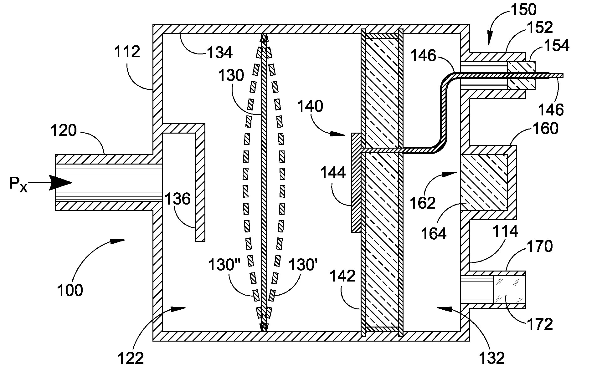
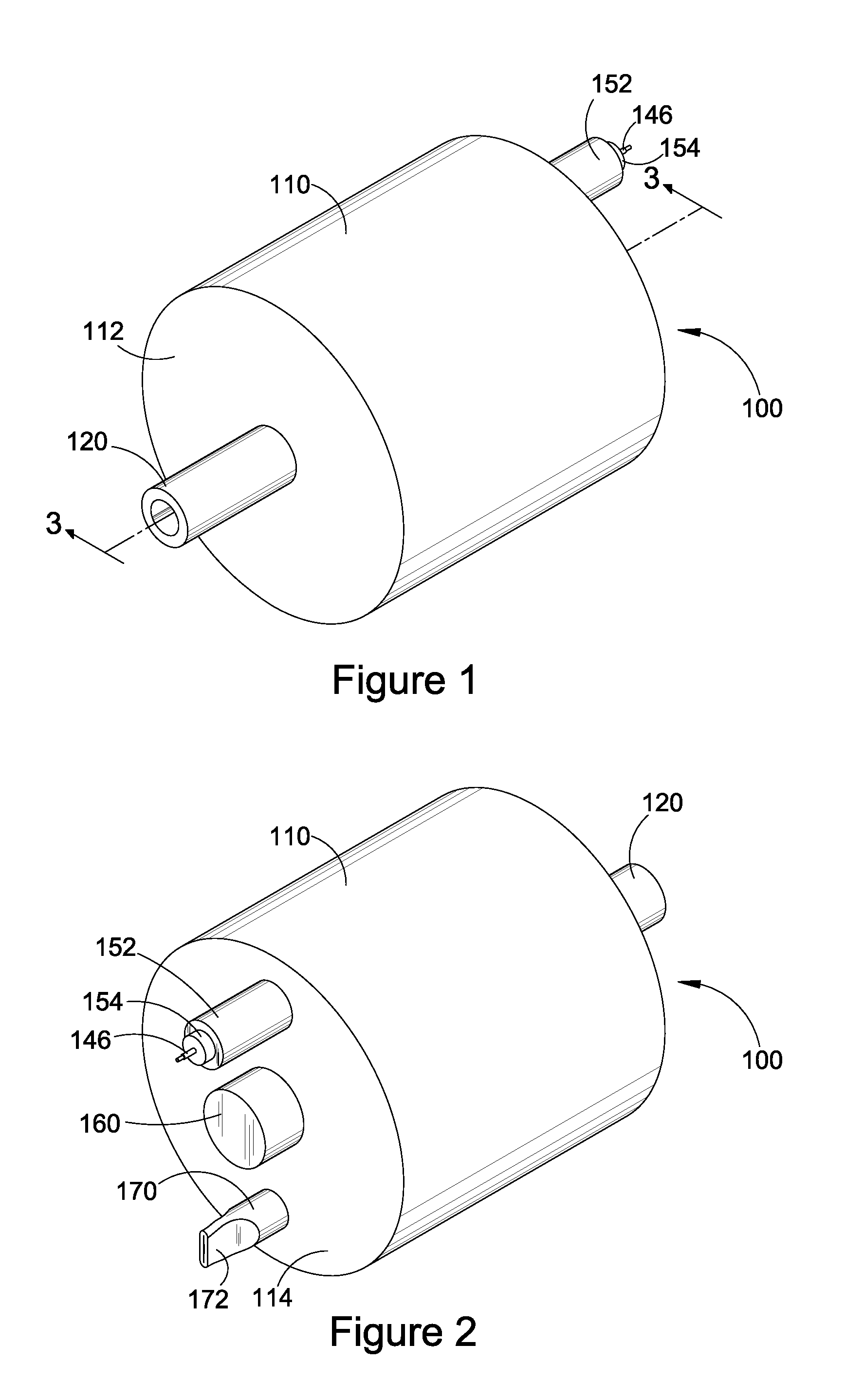
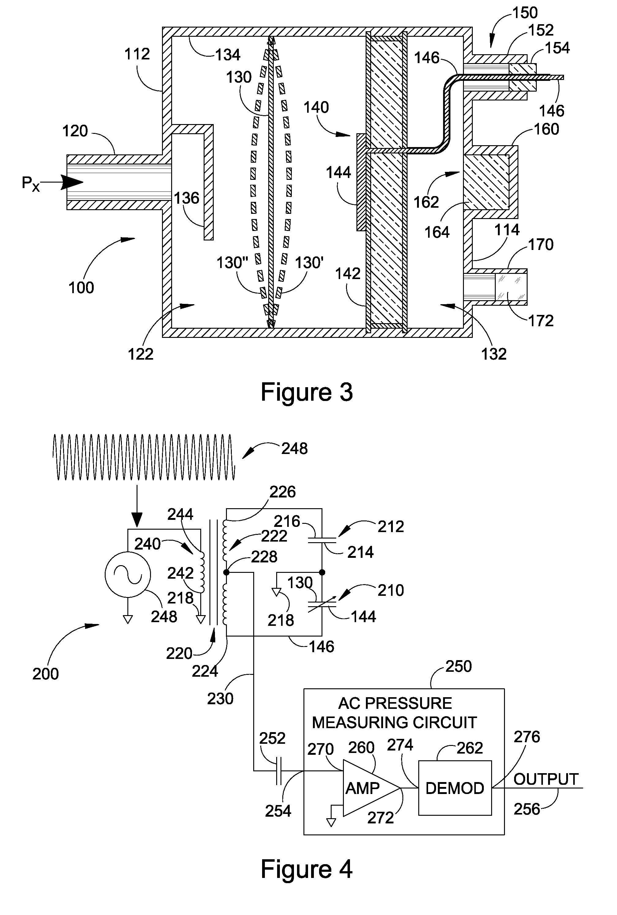
[0030]FIG. 1 illustrates a front perspective view of an exemplary capacitance diaphragm gauge (CDG) 100, which is installable into a pneumatic system (not shown) to measure the pressure within the system. In particular, the CDG is used to measure very low pressures resulting from evacuation of the pneumatic system. FIG. 2 illustrates a rear perspective view of the CDG of FIG. 1 which is rotated 180° from the view in FIG. 1. FIG. 3 illustrates a cross-sectional view of the CDG taken ...


PUM


Abstract

A system and method detect the presence of an unacceptable quantity of gas molecules in the reference vacuum cavity of a capacitance diaphragm gauge (CDG). An independent pressure transducer has an active portion exposed to the reference vacuum cavity. The transducer includes a ring anode, a cylindrical inner wall surface that forms at least one cathode, and a magnet positioned with respect to the ring anode such that the magnetic flux of the magnet is generally aligned with the central axis of the ring anode. A high voltage source applies a voltage between the ring anode and the cathode. A current sensor senses a magnitude of any current flowing between the ring anode and the cathode via ionized gas molecules. A monitoring unit monitors the magnitude of the current sensed by the current sensor and activates an alarm when the magnitude of the current exceeds an acceptable magnitude.

Description

RELATED APPLICATIONS[0001]The present application claims the benefit of priority under 35 USC §119(e) to U.S. Provisional Application No. 61 / 754,120 filed on Jan. 18, 2013, which is incorporated by reference herein.BACKGROUND OF THE INVENTION[0002]1. Field of the Invention[0003]The present invention is in the field of capacitance diaphragm gauges which measure pressure based on the deflection of a diaphragm.[0004]2. Description of the Related Art[0005]Absolute capacitance diaphragm gauges (CDGs) measure pressure by sensing the capacitance change associated with deflection of a diaphragm whereby one side of the diaphragm (“the Px side”) is exposed to the pressure to be measured (Px) and the other side of the diaphragm is exposed to a sealed reference vacuum cavity in which an ultrahigh vacuum (e.g., less than 10−9 Torr) has been created prior to the sealing of the reference cavity.[0006]The CDG measures capacitance between a diaphragm and one or more fixed electrodes housed in the re...

Claims


Application Information

Patent Timeline
IPC IPC(8): G01L9/00G01L9/12
CPCG01L9/0072G01L9/0075G01L9/14G01L21/00G01L21/34
Inventor FERRAN, DAVID J.FERRAN, ROBERT J.
Owner SUMITOMO SHI CRYOGENICS OF AMERICA
Why Eureka
Try Eureka