Integrated thin film evaporation thermal spreader and planar heat pipe heat sink

a technology of integrated thin film evaporation and heat sink, which is applied in the direction of basic electric elements, semiconductor devices, lighting and heating apparatus, etc., can solve the problems of insufficient applicability, large heat dissipation difficulty, and severe problems in the 3d die stack

Inactive Publication Date: 2014-07-24
PALO ALTO RES CENT INC
View PDF6 Cites 13 Cited by
  • Summary
  • Abstract
  • Description
  • Claims
  • Application Information

AI Technical Summary

Benefits of technology

[0022]In accordance with another aspect of the present application, a heat dissipation method to provide thermal spreading and cooling for a heat-producing body is provided. By a thin film evaporator in thermal communication with the heat-producing body, heat from the heat-producing body is removed using a working fluid. By a heat pipe integrated with

Problems solved by technology

However, increasingly, 3D architectures (e.g., with heat fluxes approaching 100 watts per square centimeter (W/cm2)) have made this approach insufficient.
3D die stacks have severe problems with hotspots on each of the layers.
Spreading this heat is a major challenge since the typical combination of solder balls, (relatively) low thermal conductivity filler and copper-filled through silicon vias (TSVs) does not provide a sufficiently conductive thermal path.
Further, spreading the heat only partially solves the problem as the heat still needs to be dissipated to the environment.
This former realization demonst

Method used


Image

  • Integrated thin film evaporation thermal spreader and planar heat pipe heat sink
  • Integrated thin film evaporation thermal spreader and planar heat pipe heat sink
  • Integrated thin film evaporation thermal spreader and planar heat pipe heat sink

Examples


Embodiment Construction

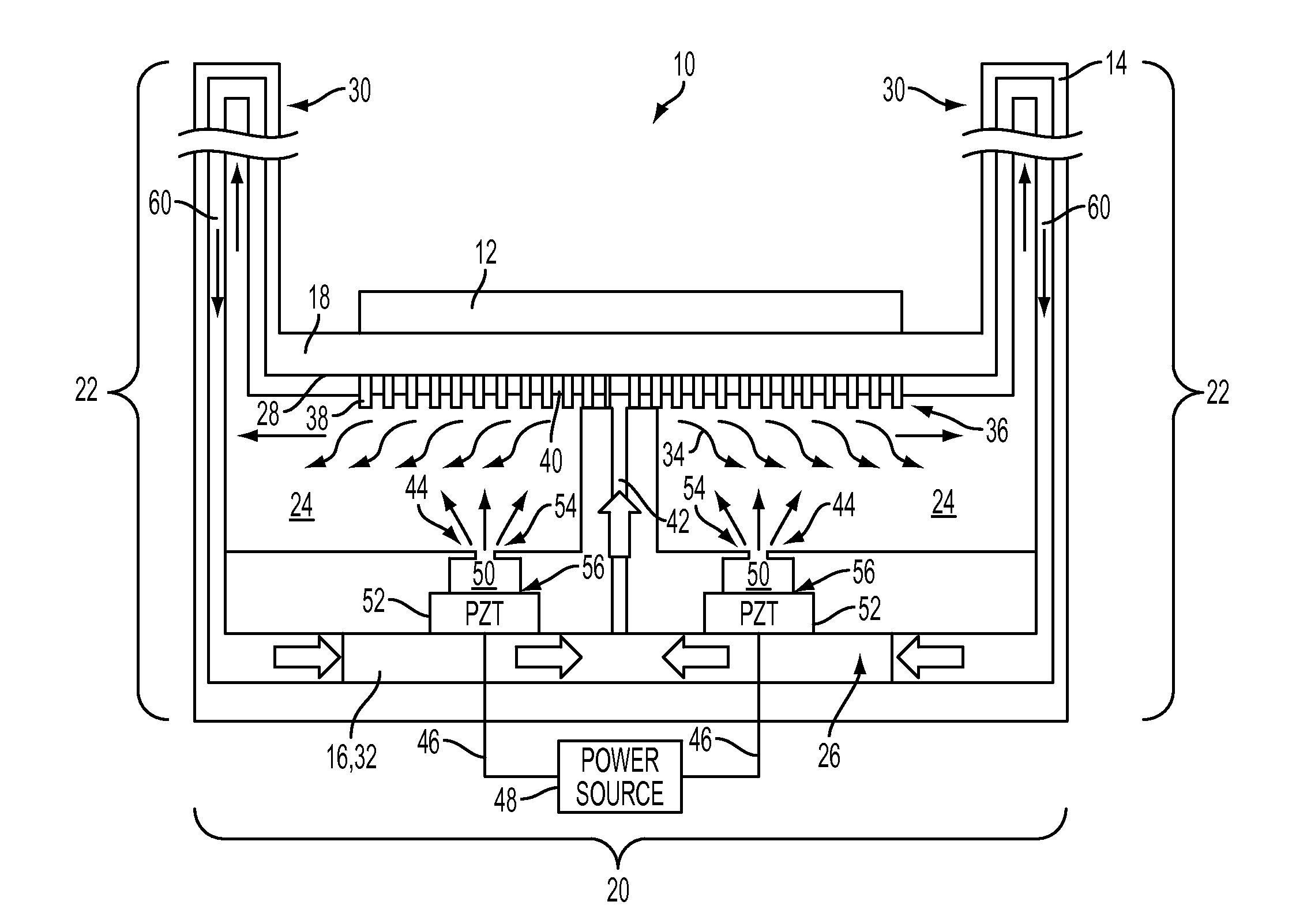
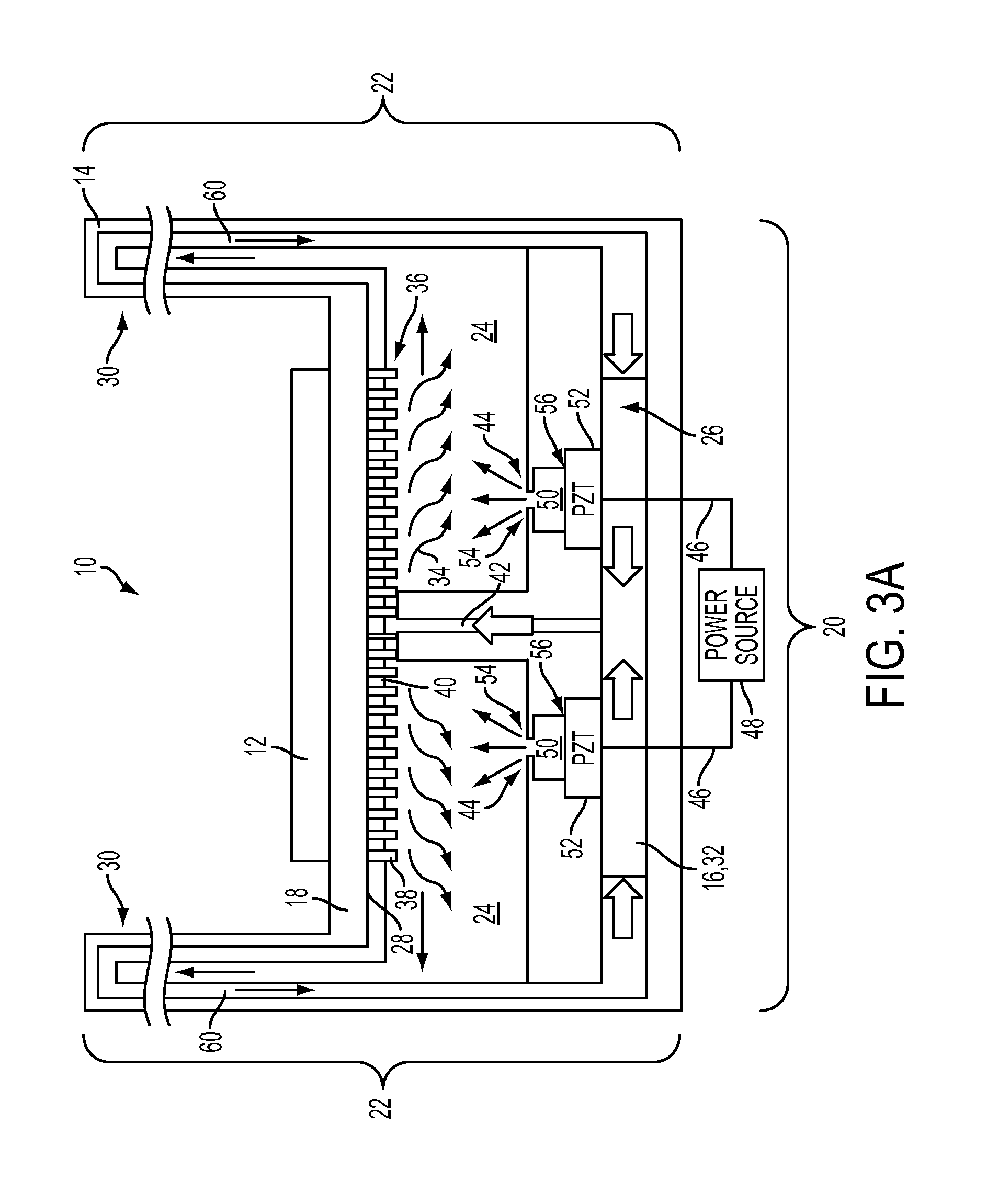
[0032]This present application combines an actively driven thin film evaporator for spreading heat with an integrated planar heat pipe extended surface for heat sinking. The thin film evaporator allows for a high rate of heat removal to remove hot spots, and the integrated planar heat pipe transports heat from the thin film evaporator to an extended surface for dissipation to the environment or sinking to an interposer layer.

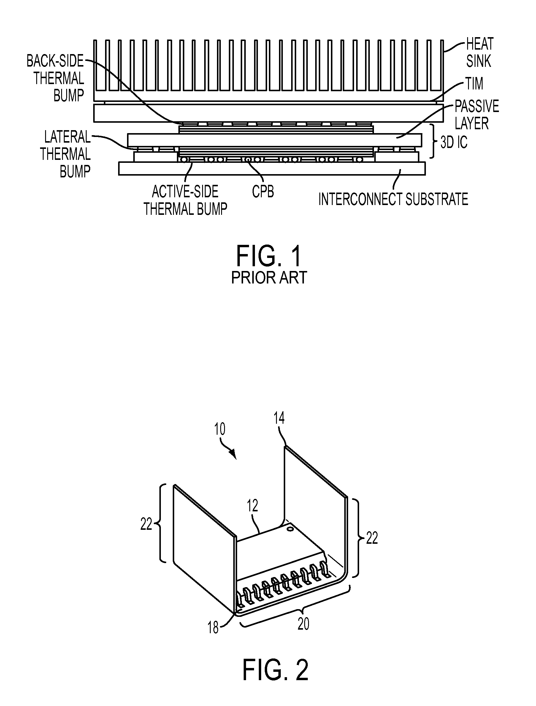
[0033]With reference to FIG. 2, a perspective view of a heat dissipation device 10 of the present application is provided. The heat dissipation device 10 provides thermal spreading and cooling to an associated heat-producing body 12, such as an integrated circuit (IC) package (illustrated). Typically, but not necessarily, the IC package is three-dimensional (3D). As will be seen, the heat dissipation device 10 is capable of managing heat fluxes of 10 to 1000 Watts per square centimeter (W / cm2) or more, such as 100 W / cm2.

[0034]The heat dissipation device 10 inclu...


PUM


Abstract

A heat dissipation device and method provides thermal spreading and cooling for a heat-producing body. A thin film evaporator in thermal communication with the heat-producing body removes heat from the heat-producing body using a working fluid. A heat pipe integrated with the thin film evaporator, and extending from the thin film evaporator, dissipates heat removed by the thin film evaporator to the external environment of the heat dissipation device. A pumping element at least one of: 1) pumps working fluid to the thin film evaporator; and 2) augments transfer of working fluid to the thin film evaporator.

Description

BACKGROUND[0001]The present application relates generally to thermal management. It finds particular application in conjunction with cooling heat-producing bodies, such as integrated circuits, and will be described with particular reference thereto. However, it is to be appreciated that the present application is also amenable to other like applications.[0002]Thermal management for electronics packaging is an active area of research given the increasing demands for high power density and three-dimensional (3D) integrated circuit (IC) architectures. With reference to FIG. 1, a typical electronics package for a 3D IC is shown. As can be seen, the electronics package relies upon a passive heat sink for thermal management.[0003]Most approaches for electronics gaseous working fluid thermal management are focused on back-side thermal management. An example of such an approach is described in U.S. Patent Application Publication No. 2005 / 0280162 to Mok et al. which describes an integrated v...

Claims


Application Information

Patent Timeline
IPC IPC(8): F28D15/02
CPCF28D15/02H01L23/427H01L23/4735H01L2924/0002F28D15/0233F28D15/0266F28D15/046H01L2924/00
Inventor PASCHKEWITZ, JOHN STEVEN
Owner PALO ALTO RES CENT INC
Why Eureka
Try Eureka