Radiographic apparatus and an image processing method therefore

a radiation apparatus and image processing technology, applied in the direction of material analysis using wave/particle radiation, instruments, nuclear engineering, etc., can solve the problem that the computation time of nonlinear optimization operation becomes long with increasing the number of parameters, and achieves the convergence accuracy of nonlinear optimization operation, the effect of limiting the number of parameters and ensuring the speed of calculation

Active Publication Date: 2014-07-24
SHIMADZU CORP
View PDF3 Cites 20 Cited by
  • Summary
  • Abstract
  • Description
  • Claims
  • Application Information

AI Technical Summary

Benefits of technology

[0033]According to the radiographic apparatus in this in this invention and the image processing method therefor, at the time of parameter calculation, based on the radiographic conditions when the phantom for correction is radiographed, the number of parameters limiting device reduces and limits the number of parameters to be calculated by nonlinear optimization operation. Thus, based on the known radiographic conditions, initial values of the parameters representing the geometric relationship between the radiation emitting device, stage and r

Problems solved by technology

The conventional methods include no proposal concerning a speed-up method tackling a problem that compu

Method used


Image

  • Radiographic apparatus and an image processing method therefore
  • Radiographic apparatus and an image processing method therefore
  • Radiographic apparatus and an image processing method therefore

Examples


embodiment

[0048]An embodiment of this invention will be described hereinafter with reference to the drawings.

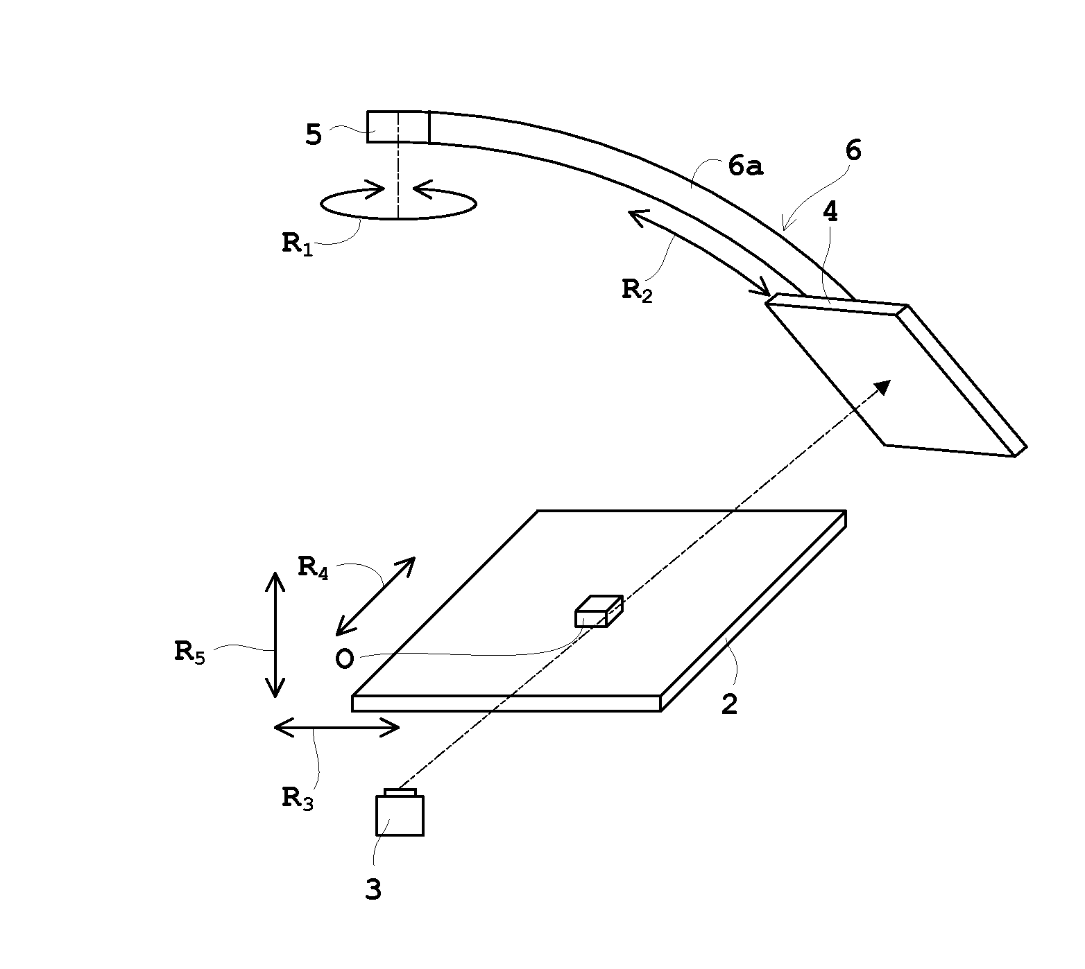
[0049]FIG. 4 is an outline schematic view of an X-ray inspection apparatus according to the embodiment. FIG. 5 is an outline perspective view of the X-ray inspection apparatus according to the embodiment. FIG. 6 is an outline perspective view of the X-ray inspection apparatus according to the embodiment illustrating a calibration method with a phantom for correction. FIG. 7 is an outline perspective view of the X-ray inspection apparatus according to the embodiment illustrating each coordinate system. FIG. 8 is a block diagram of the X-ray inspection apparatus according to the embodiment. In this embodiment, the X-ray inspection apparatus will be described as an example of radiographic apparatus.

[0050]As shown in FIG. 4, the X-ray inspection apparatus 1 includes a stage 2 for holding an object O, and an X-ray tube 3 and an X-ray detector 4 arranged opposite each other across the stage ...


PUM


Abstract

Initial values Â1P̂1M̂1 . . . ÂnP̂nM̂n of parameters representing a geometric relationship between an X-ray tube, a stage and a flat panel X-ray detector are estimated, a least squares solution (p̂w)i of characteristic point three-dimensional coordinates is estimated, and only limited parameters are updated until reprojection square errors converge. Thus, based on known radiographic conditions, initial values of the parameters are estimated, and a nonlinear optimization operation is carried out on only the parameters considered, in view of mechanisms and drive characteristics of the apparatus, to have large errors between the initial values of the parameters and the parameters at a time when radiography is actually carried out. As a result, the calculation can be speeded up, while securing the convergence accuracy of the nonlinear optimization operation, by using the radiographic conditions, i.e. information on tomography.

Description

TECHNICAL FIELD[0001]This invention relates to a radiographic apparatus and an image processing method therefor, for performing radiography based on projection images obtained by detecting, with a radiation detecting device, radiation emitted from a radiation emitting device and transmitted through an object.BACKGROUND ART[0002]Description will be made taking X-rays as an example of radiation. The object may be a mounted substrate, a through hole / pattern / solder joint of a multilayer substrate, an electronic component before mounting such as an integrated circuit (IC) arranged on a palette, a casting such as of metal, or a molded article such as a videocassette recorder. Specifically, it is used for inspection of electronic components (eg inspection of wiring on substrates, and inspection of BGA (Ball Grid Array), solder joints, voids) and for inspection of internal defects of these objects.[0003]With a CT (Computed Tomography) apparatus known conventionally, as shown in FIG. 1, an o...

Claims


Application Information

Patent Timeline
IPC IPC(8): G01N23/04
CPCG01N23/046G01N2223/3304G01N2223/419G01N2223/6113G06T11/005
Inventor TAGAWA, YUSUKE
Owner SHIMADZU CORP
Why Eureka
Try Eureka