
Tie rod support for hydraulic hammer

Inactive Publication Date: 2014-07-31
CATERPILLAR INC
View PDF8 Cites 35 Cited by
  • Summary
  • Abstract
  • Description
  • Claims
  • Application Information

AI Technical Summary

Benefits of technology

This patent describes a powered hammer assembly that includes a front head with nut pockets and a tie rod nut inserted in one direction and a tie rod inserted in another direction, which is mechanically attached to the nut. The assembly also includes a structure that engages the nut pocket and opposes motion in the opposite direction. The patent also describes a mounting structure for the hammer head that includes four nut pockets, tie rod bores, and tie rod nuts and rods that are mechanically attached to each other. The technical effects of this patent include improved controllability, durability, and efficiency of the powered hammer assembly.

Problems solved by technology

The high impact and repetitive nature of operating a hydraulic hammer is hard on its component parts which may suffer stresses resulting in bending or breaking.
Repairing these components can be difficult and time consuming, particularly when components are bent or are forced out of alignment.

Method used


Image

  • Tie rod support for hydraulic hammer
  • Tie rod support for hydraulic hammer
  • Tie rod support for hydraulic hammer

Examples


Embodiment Construction

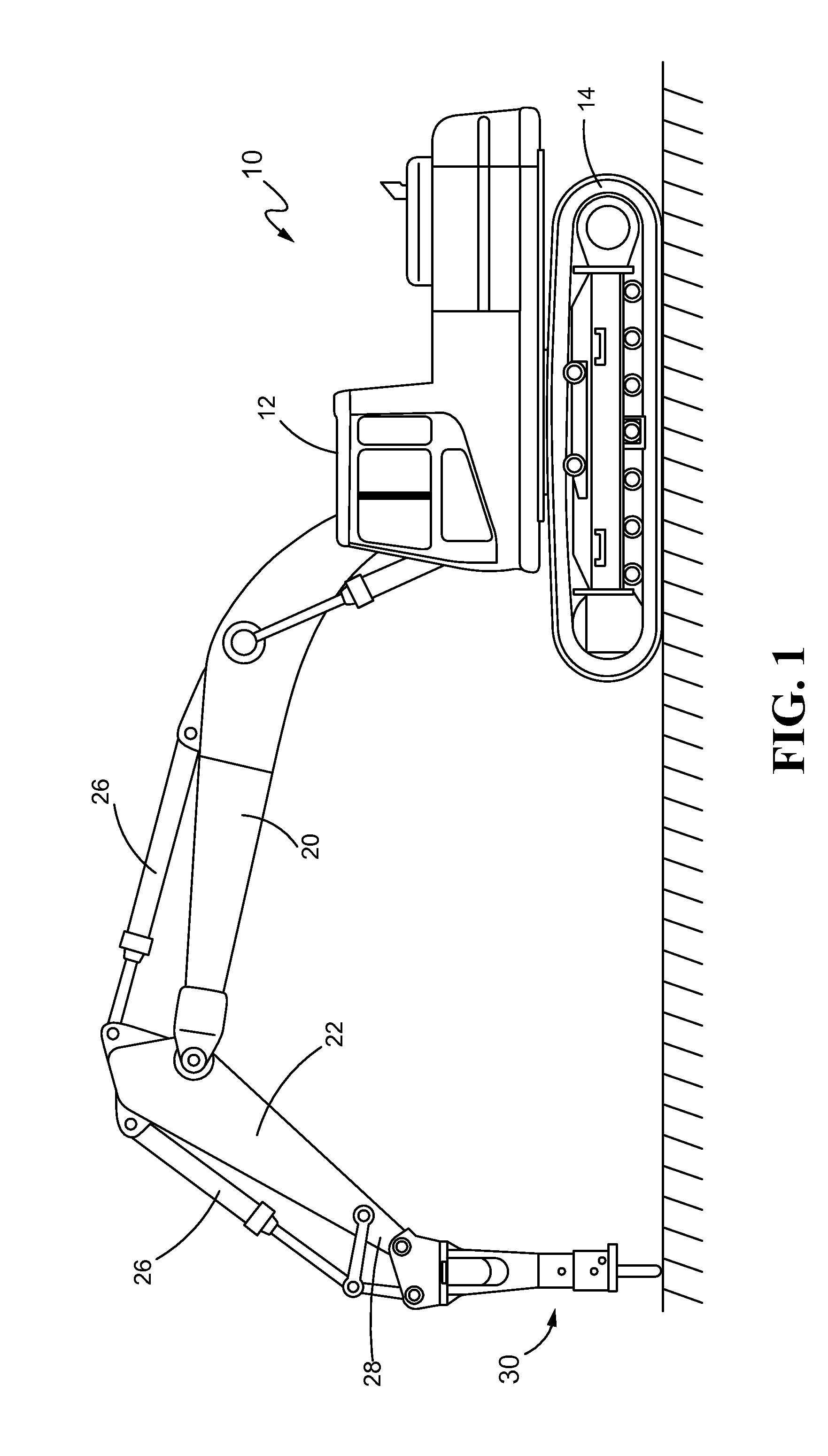
[0020]Referring initially to FIG. 1, an excavating machine 10 of a type used for digging and removing rock and soil from a construction worksite is shown. The excavating machine 10 may incorporate a cab body 12 containing an operator station, an engine, and operating controls (not depicted). The machine 10 may be supported by, and may move on, tracks 14. An extensible boom 20 may be movably anchored to the cab body 12, and an articulating stick 22, also variously called a lift arm, may be secured to and supported for movement on the boom 20.

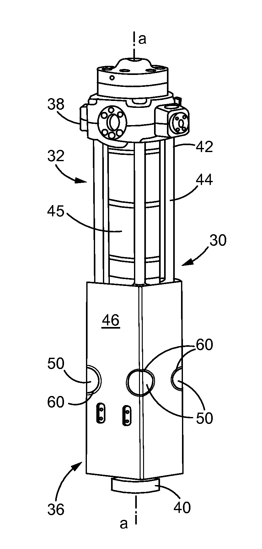
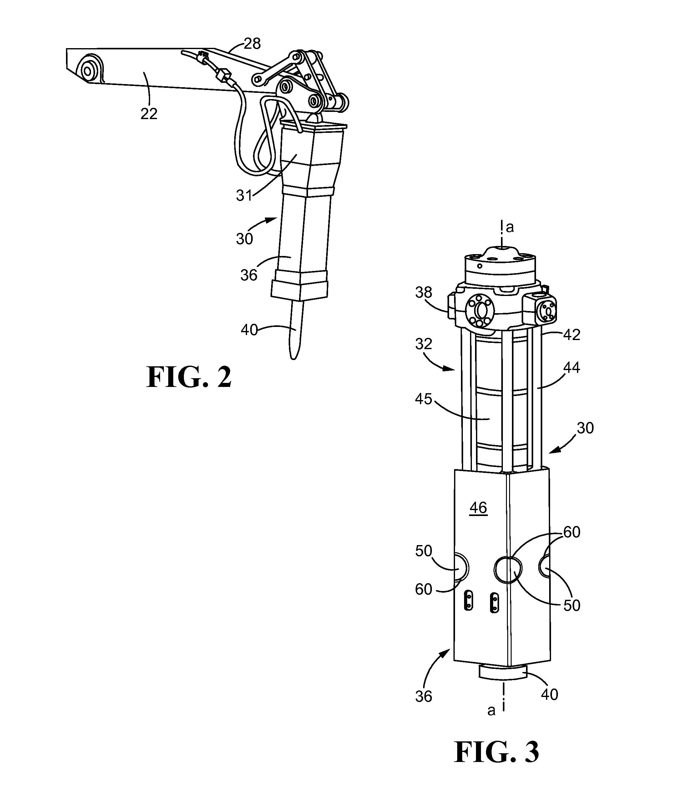
[0021]The excavating machine 10 may incorporate a hydraulic hammer 30 as depicted, or may alternatively incorporate another implement, at an operational end 28 of the stick 22. Hydraulic cylinder actuators 26 may be utilized to move the stick 22 relative to the boom 20, and to move hydraulic hammer 30 relative to the stick 22.

[0022]Referring now also to FIG. 2, a fluid powered hammer assembly, although herein called a hydraulic hammer assembly 30...


PUM

PropertyMeasurementUnit
Forceaaaaaaaaaa
Pressureaaaaaaaaaa
Structureaaaaaaaaaa

Abstract

A hydraulic hammer may include a power cell adapted to reciprocally drive a piston along an axis. The piston may, in turn, drive a hammer tool. A power cell and housing may be axially secured together by a plurality of tie rods and nuts secured to ends of the tie rods, and the housing may include open-sided pockets for accommodating the nuts. Each pocket may include a cavity that accommodates an extension of the tie rod or a specially formed nut to minimize movement of the nut in the direction of the pocket opening and thereby minimize bending of the tie rod. Engaging the back of the nut with the inside of the nut pocket further reduces the opportunity for the nut to rotate in the nut pocket as a result of force applied to the nut by the tie rod.

Description

TECHNICAL FIELD[0001]This disclosure relates to design improvements for optimizing longevity and / or reducing the maintenance and / or replacement of parts in hydraulic hammers subjected to harsh cyclic stresses. More particularly, the disclosure relates to an improved nut pocket configuration for the front heads of hydraulic hammers affixed to and utilized on machines.BACKGROUND[0002]Hydraulic hammers are generally employed on worksites to demolish and break up hard objects, including rocks, concrete, asphalt, and frozen ground. The hammers may be mounted to machines, such as excavators and backhoes, for example. The hammers may alternatively be powered by pneumatic pressure sources, as opposed to only hydraulic sources. In either event, a high-pressure fluid may be utilized within the hammer to cyclically drive a piston to strike a work tool, which in turn may carry an impulse wave to the object of demolition for breaking that object into smaller pieces, generally for easier removal ...

Claims


Application Information

Patent Timeline
IPC IPC(8): F16B41/00E02F5/30
CPCE02F5/305F16B41/002E02F3/966Y10T29/49948
Inventor JAGDALE, RAKESH D.FORTNER, FRANCIS ERICAMBORSKI, STEPHENDOSTINOV, DIMITAR
Owner CATERPILLAR INC
Features
  • Generate Ideas
  • Intellectual Property
  • Life Sciences
  • Materials
  • Tech Scout
  • Unparalleled Data Quality
  • Higher Quality Content
  • 60% Fewer Hallucinations
Learn More