
Metal-insulator transition (MIT) device molded by clear compound epoxy and fire detecting device including the mit device

a technology of metal-insulator transition and clear compound epoxy, which is applied in the direction of resistor housing/enclose/embedding, fire alarms, instruments, etc., can solve the problems of not being able to operate at a predetermined set temperature, aluminum plate may have high cost, and high standby current, so as to increase or maximize productivity, reduce the effect of aluminum plate cost and high cos

Active Publication Date: 2014-07-31
ELECTRONICS & TELECOMM RES INST
View PDF30 Cites 6 Cited by
  • Summary
  • Abstract
  • Description
  • Claims
  • Application Information

AI Technical Summary

Benefits of technology

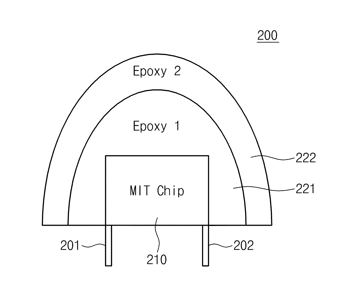
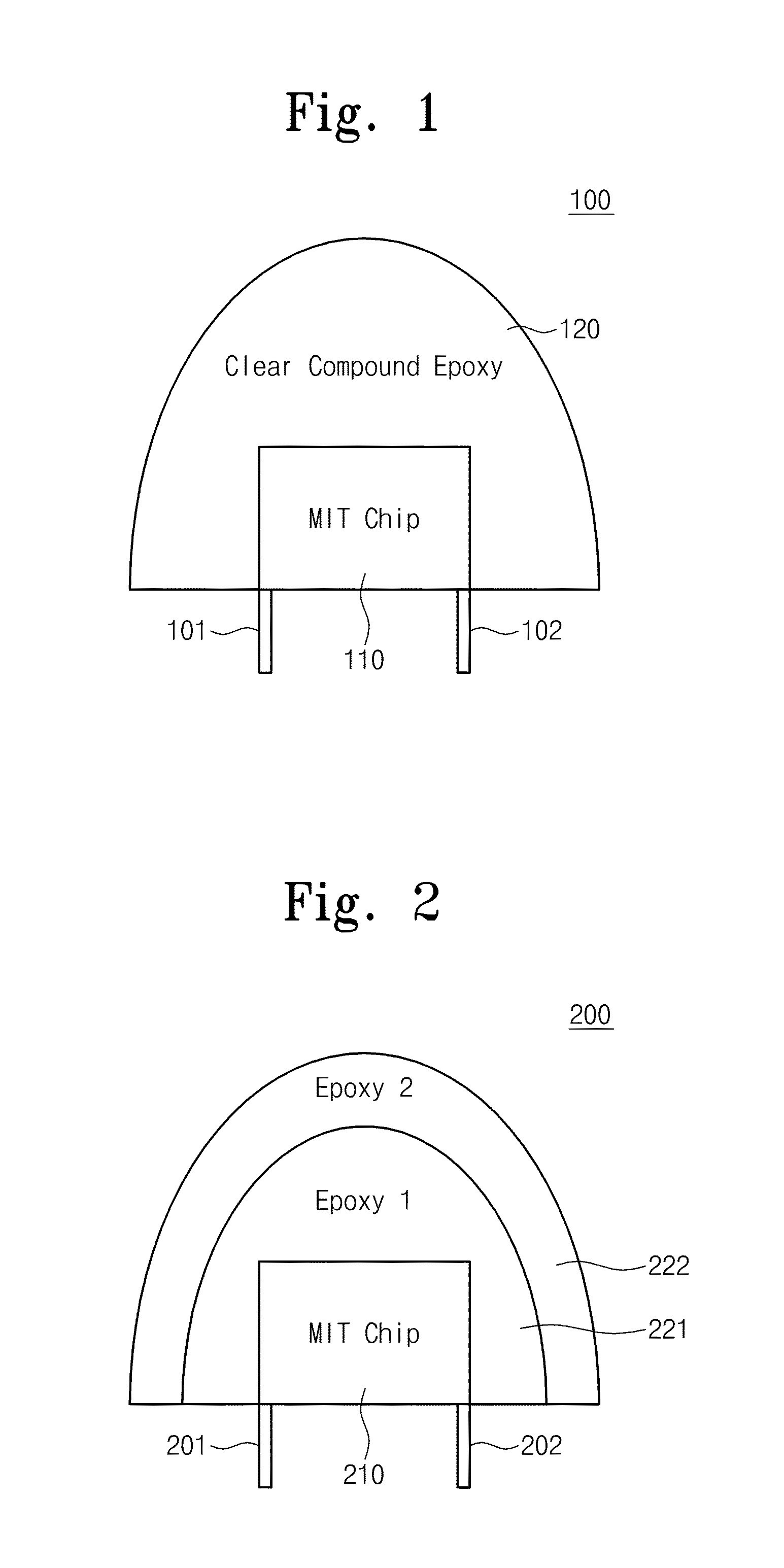
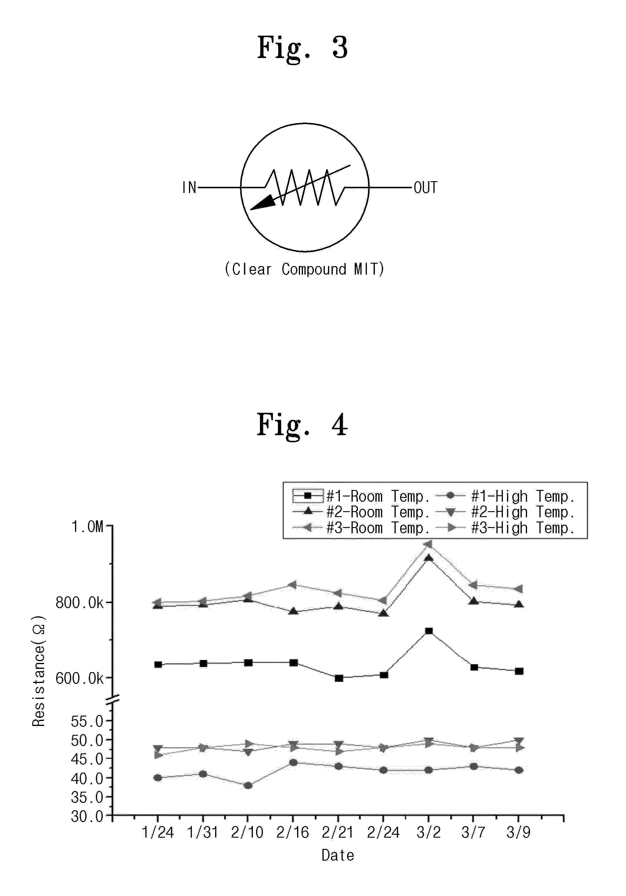
The invention uses a temperature-sensitive layer made of vanadium oxide as the active layer of a smoke sensor. This increases stability and productivity. The use of two epoxies protects the first one and maximizes stability. The device is controlled by voltage to control its operation temperature, allowing it to more quickly respond to hot wind conditions. As a result, the MIT device is more efficient and effective in detecting smoke.

Problems solved by technology

According to the constant temperature type fire detector using the bimetal, aluminum may be oxidized at a contact point of the bimetal, so that it may not be operated at a predetermined set temperature.
Additionally, an aluminum plate may have high cost.
The constant temperature type fire detector using the thermistor may use three or more grounds, so that a stand by current may be great.
Additionally, the constant temperature type fire detector using the thermistor may include ten parts for detecting a constant temperature, so that manufacture cost may increase.
Furthermore, when the constant temperature type fire detector using the thermistor is operated for a long time, trouble rates of the parts may increase and durability of the parts may be deteriorated.
Thus, alternative methods for solving the above problems have been required for a long time.

Method used


Image

  • Metal-insulator transition (MIT) device molded by clear compound epoxy and fire detecting device including the mit device
  • Metal-insulator transition (MIT) device molded by clear compound epoxy and fire detecting device including the mit device
  • Metal-insulator transition (MIT) device molded by clear compound epoxy and fire detecting device including the mit device

Examples


Embodiment Construction

Technical Problem

[0003]Embodiments of the inventive concept may provide fire detectors which are capable of minimizing power consumption in ordinary times for being operated by a low power and have high reliability for a long time.

[0004]Embodiments of the inventive concept may also provide fire detectors capable of improving accuracy by reducing a cause disturbing normal operations of a resistance value and a setting temperature for a long time.

[0005]Embodiments of the inventive concept may also provide fire detector modules more responding to an ascending atmospheric current caused in a fire and reducing production cost by replacing a part used in a circuit with new one.

Technical Solution

[0006]According to embodiments of the inventive concepts, a metal-insulator transition (MIT) device includes: a MIT chip having a material causing a metal-insulator transition (MIT) phenomenon at a critical temperature; and a clear compound epoxy molding the MIT chip.

[0007]In some embodiments, the ...


PUM


Abstract

The inventive concept provides MIT devices molded by clear compound epoxy and fire detecting devices including the MIT device. The fire detecting device is supplied with a power source from a power control device. The fire detecting device includes a MIT device including a MIT chip molded by a clear compound epoxy, a diode bridge circuit supplied with the power source from the power control device for providing a non-polar power source, a notice circuit supplied with the non-polar power source from the diode bridge circuit for warning of a fire alarm in response to a detecting signal from the MIT device, and a stabilization circuit for maintaining the detecting signal for a certain period.

Description

TECHNICAL FIELD[0001]The inventive concept relates to a MIT device and a fire detecting device including the MIT device and, more particularly, to a MIT device molded by a clear compound epoxy and a fire detecting device including the MIT device.BACKGROUND ART[0002]It is significant to manufacture a constant temperature type fire alarm detector operated by a lower power, as green technology. Constant temperature type fire detectors may be operated by a method using a bimetal or a method using a thermistor. According to the constant temperature type fire detector using the bimetal, aluminum may be oxidized at a contact point of the bimetal, so that it may not be operated at a predetermined set temperature. Additionally, an aluminum plate may have high cost. The constant temperature type fire detector using the thermistor may use three or more grounds, so that a stand by current may be great. Additionally, the constant temperature type fire detector using the thermistor may include te...

Claims


Application Information

Patent Timeline
Patent Type & Authority Applications(United States)
IPC IPC(8): H01L49/00G08B17/06H10N99/00
CPCG08B17/06H01L49/003H01C1/02H01C7/047H10N99/03H01H37/32H01L27/0248H01L27/0647H02H9/045
Inventor KIM, HYUN-TAKKIM, BONGJUNPARK, JONG CHAN
Owner ELECTRONICS & TELECOMM RES INST
Learn More