Charge Pump Circuit and Memory

a charge pump and circuit technology, applied in the field of circuit design technology, can solve the problems of not meeting the high-level integration of the circuit, increasing the size reducing so as to reduce the power consumption of the charge pump circuit. , the effect of limited driving ability

Active Publication Date: 2014-07-31
SHANGHAI HUAHONG GRACE SEMICON MFG CORP
View PDF7 Cites 2 Cited by
  • Summary
  • Abstract
  • Description
  • Claims
  • Application Information

AI Technical Summary

Benefits of technology

[0016]Compared with the conventional solutions, the present disclosure may have following advantages. In the charge pump circuit provided in the present disclosure, a leakage current load is detected to control a clock driving signal output by a clock driving unit, so that the frequency of the clock driving signal varies with the leakage current load automatically. During a beginning time period after the charge pump circuit starts to work, since the detected leakage current load is relatively low, the clock driving signal output by the clock driving unit may have a low frequency. With the gradually increased detected leakage current load, the clock driving signal may have a gradually increased frequency correspondingly.
[0017]During the beginning time period after the charge pump circuit starts to work, an output voltage of the charge pump circuit rises rapidly. And due to a low frequency of the clock driving signal, a peak current is reduced and further power consumption of the charge pump circuit is reduced. When the leakage current load rises, the frequency of the clock driving signal rises, so that a required leakage current load can be met without increasing a size of the charge pump circuit. Besides, a driving ability of the charge pump circuit may be limited because of the rise in the leakage current load, thus, the leak current is low and the power consumption will not be increased although the frequency of the clock driving signal rises.

Problems solved by technology

However, the capacitor with great capacitance may increase a size of the charge pump circuit, which does not satisfy a high-level integration of a circuit.
Besides, a driving ability of the charge pump circuit may be limited because of the rise in the leakage current load, thus, the leak current is low and the power consumption will not be increased although the frequency of the clock driving signal rises.

Method used


Image

  • Charge Pump Circuit and Memory
  • Charge Pump Circuit and Memory
  • Charge Pump Circuit and Memory

Examples


Embodiment Construction

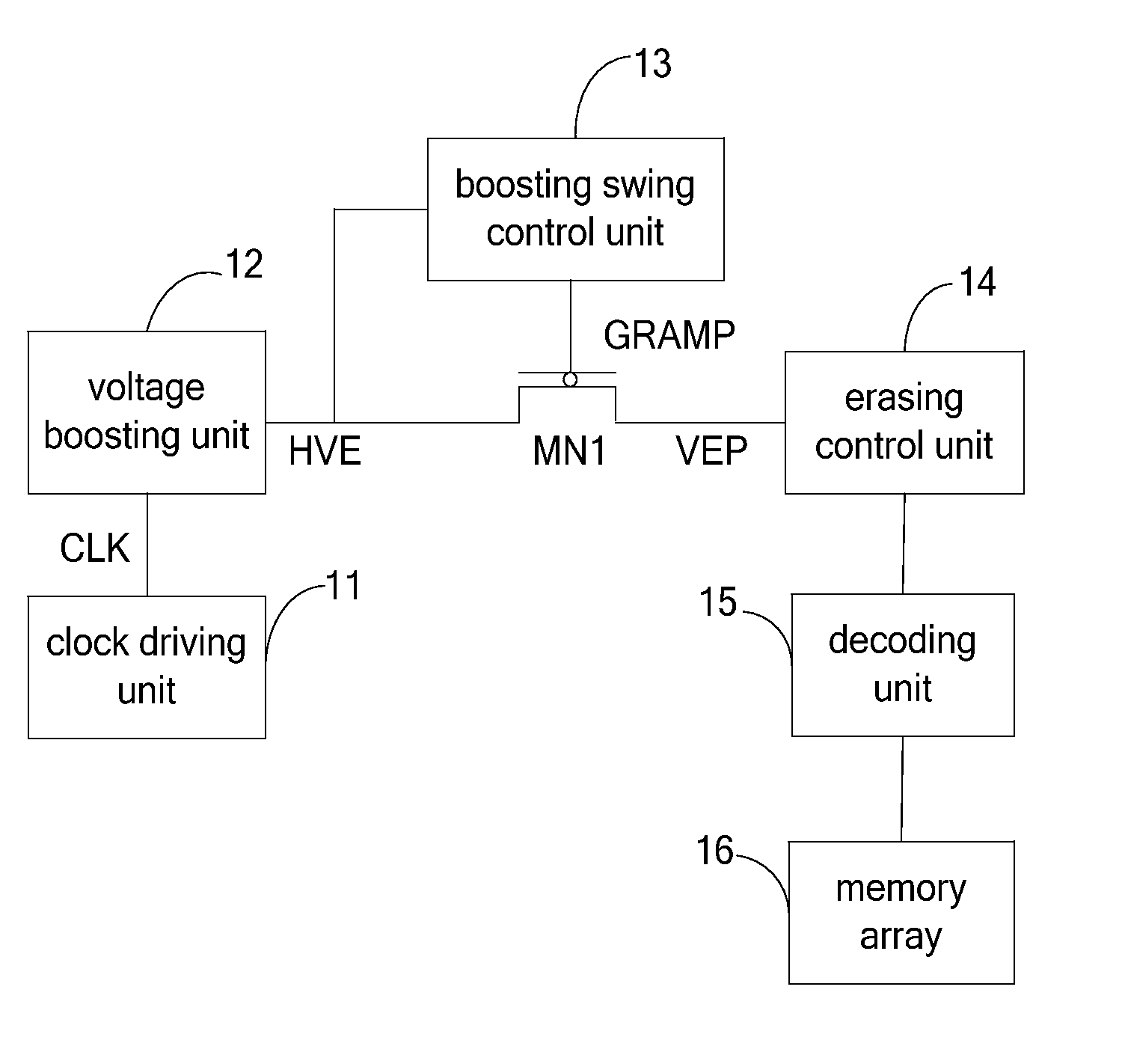
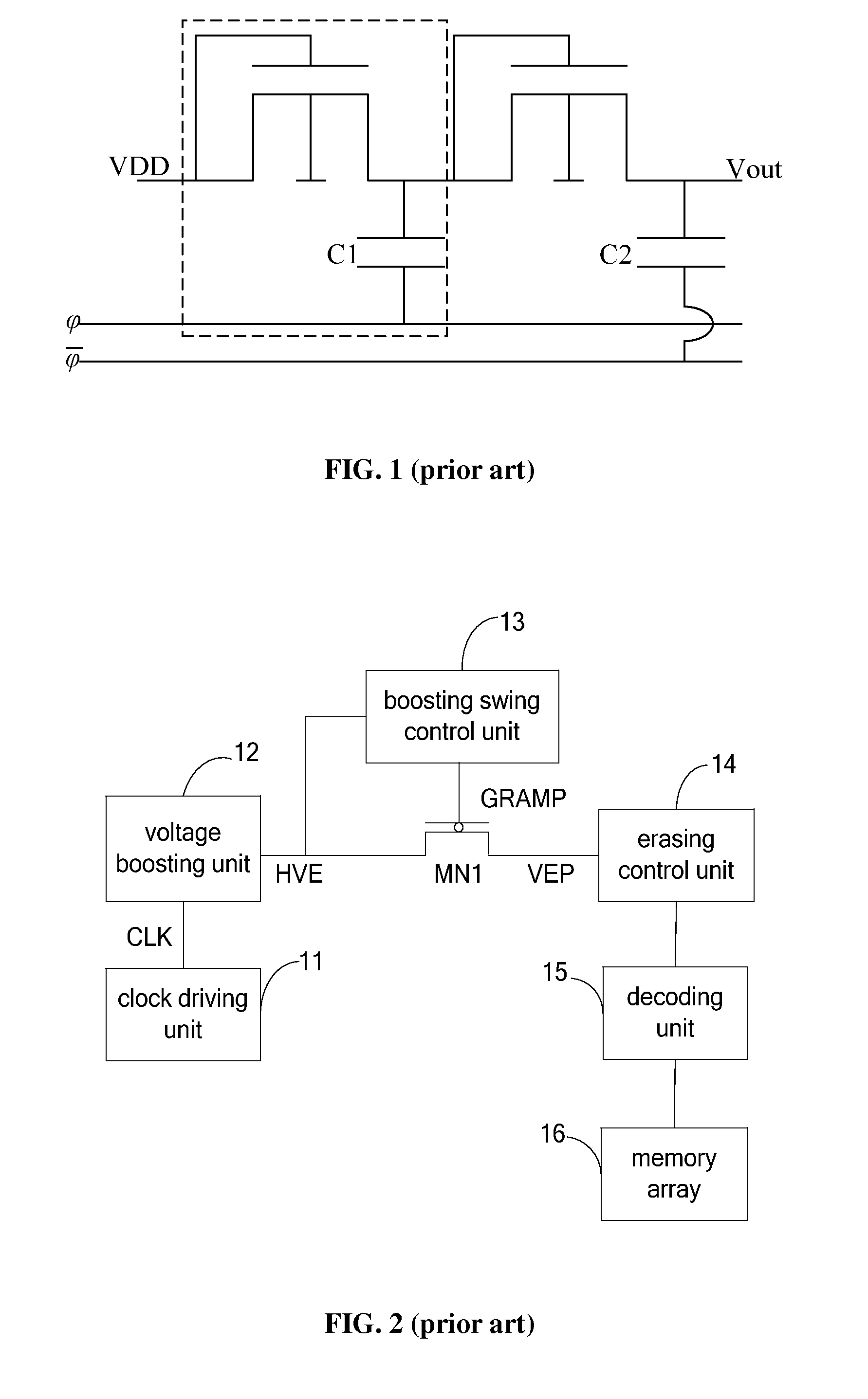
[0024]As described in background, in conventional charge pump circuits, to satisfy a requirement on a leak current and reduce power consumption, a frequency of a clock driving signal output by a clock driving unit is reduced. When a charge pump circuit is applied in a memory to provide a voltage for programming or erasing for the memory, leakage currents in a memory array and a decoding circuit constitute a leakage current load of the charge pump circuit. To satisfy a requirement on the leakage current load and keep a charge transfer amount among stages of the charge pump circuit unchanged, a capacitor with great capacitance is required in each stage of charge pump circuit to store a large amount of charges. However, the capacitor with great capacitance may increase a size of the charge pump circuit, which does not satisfy a high-level integration of a circuit. Therefore, a charge pump circuit with a small size and low power consumption is provided in the present disclosure.

[0025]In...


PUM


Abstract

Charge pump circuit and memory are provided. The charge pump circuit includes a clock driving unit, a voltage boosting unit, a boosting swing control unit, a first and second NMOS tubes, a first and second current mirror units. The clock driving unit is adapted to form and output clock driving signals to the voltage boosting unit. The voltage boosting unit is adapted to boost voltage and output it to the boosting swing control unit and the first current minor unit. The boosting swing control unit is adapted to output boosting swing control signals to the first NMOS tube. The first current minor unit is to output first mirror current and the second current minor unit is to minor the first mirror current and output second minor current. Frequency of the clock driving signal varies with leakage current load, and size of the charge pump circuit and power consumption are reduced.

Description

CROSS-REFERENCE TO RELATED APPLICATIONS[0001]The present application claims priority to Chinese patent application No. 201310029800.1, filed on Jan. 25, 2013, and entitled “CHARGE PUMP CIRCUIT AND MEMORY”, and the entire disclosure of which is incorporated herein by reference.FIELD OF THE DISCLOSURE[0002]The present disclosure generally relates to circuit design technology, and more particularly, to a charge pump circuit and a memory.BACKGROUND OF THE DISCLOSURE[0003]With the development of semiconductor technology, semiconductor products are developed to have low power consumption and low cost, thus, a power-supply voltage of a memory is relatively low, such as 2.5V and 1.8V. However, to realize reading and writing of stored information, a voltage for programming and erasing, which is much higher than the power-supply voltage, is required, such as 8V and 11V. Therefore, charge pump circuits, which are used to generate a high voltage for programming and erasing from a low power-supp...

Claims


Application Information

Patent Timeline
Patent Type & Authority Applications(United States)
IPC IPC(8): G11C5/14
CPCG11C5/145
Inventor YANG, GUANGJUN
Owner SHANGHAI HUAHONG GRACE SEMICON MFG CORP
Why Eureka
Try Eureka