X-ray generator and x-ray imaging apparatus

a generator and x-ray technology, applied in the direction of instruments, x-ray tubes, material analysis using wave/particle radiation, etc., can solve the problem of significantly low x-ray generation efficiency, and achieve the effect of improving x-ray generation efficiency

Inactive Publication Date: 2014-07-31
CANON KK
View PDF21 Cites 57 Cited by
  • Summary
  • Abstract
  • Description
  • Claims
  • Application Information

AI Technical Summary

Benefits of technology

[0009]According to the present invention, besides the X-ray generated at the transmission target, the X-ray generated from reflected electrons generated at the transmission ta...

Problems solved by technology

Generally, in a transmission type X-ray generator which emits electrons at a transmiss...

Method used


Image

  • X-ray generator and x-ray imaging apparatus
  • X-ray generator and x-ray imaging apparatus
  • X-ray generator and x-ray imaging apparatus

Examples


first embodiment

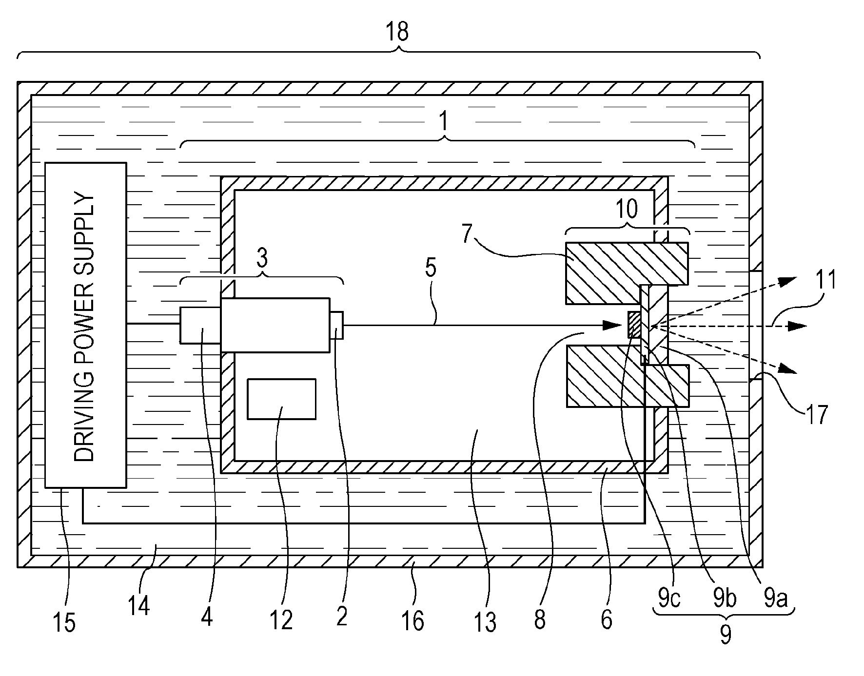
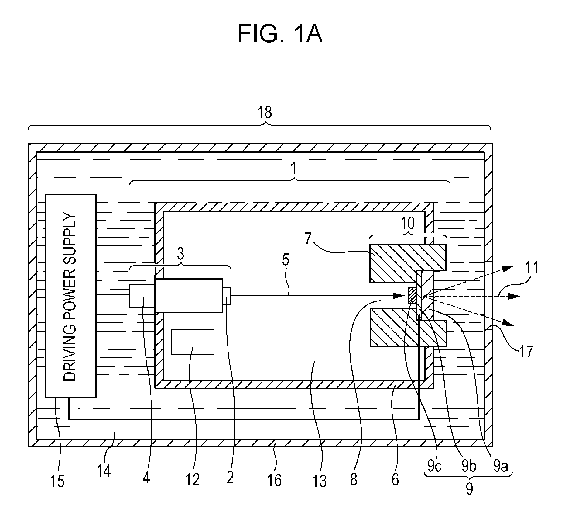
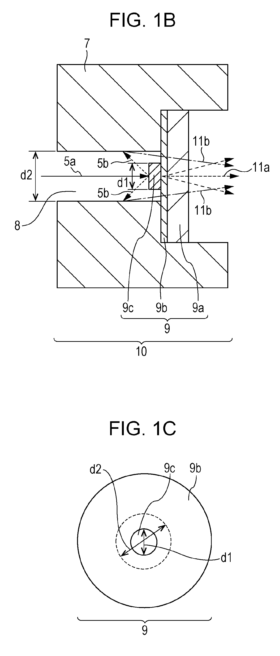
[0022]FIG. 1A is a cross-sectional view of an exemplary configuration of a transmission type X-ray generator (hereafter, “X-ray generator”) 18 according to the present embodiment. FIG. 1B is an enlarged cross-sectional view of an anode 10 illustrated in FIG. 1A. FIG. 1C is a plan view of a target area 9 illustrated in FIG. 1A seen from the target side.

[0023]The X-ray generator 18 consists of an X-ray source 1 and a driving power source 15 which are disposed in an envelope 16, and insulation oil 14 with which ullage space in the envelope 16 is filled. The envelope 16 is provided with an X-ray extraction window 17.

[0024]The X-ray source 1 consists of an electron source 3, an anode 10, a getter 12 and a vacuum vessel 6.

[0025]The electron source 3 consists of a current introducing terminal 4 and an electron emitting portion 2. A mechanism of the electron source 3 for emitting electrons may be any electron source capable of controlling the amount of electrons emitted from outside the vac...

second embodiment

[0046]A second embodiment will be described with reference to FIGS. 2A and 2B. FIG. 2A is a cross-sectional view of a target area in the transmission type X-ray generator of the present embodiment. FIG. 2B is a plan view of a target area of FIG. 2A seen from the target side.

[0047]The X-ray generator of the present embodiment is provided with the same components as those of the first embodiment and has the same configuration as that of the first embodiment except for the target area 9. As illustrated in FIG. 2A, the target area 9 is configured such that the target 9c is disposed at the central area on the substrate 9a and that the conductive layer 9b is disposed on the substrate 9a in an area other than the central area. The target 9c is connected to the conductive layer 9b. Materials of the substrate 9a, the conductive layer 9b and the target 9c may be selected in the same manner as described in the first embodiment.

third embodiment

[0048]FIG. 2C is a cross-sectional view of a target area in the X-ray generator of the present embodiment. FIG. 2D is a plan view of the target area of FIG. 2C seen from the target side.

[0049]The X-ray generator of the present embodiment is provided with the same components as those of the first embodiment and has the same configuration as that of the first embodiment except for the target area 9. As illustrated in FIG. 2C, the target area 9 of the present embodiment is configured such that the target 9c is disposed at the central area on the substrate 9a, and that the conductive layer 9b is disposed on the substrate 9a in an area other than the central area and on the target 9c. The target 9c is covered with the conductive layer 9b. Materials of the substrate 9a, the conductive layer 9b and the target 9c may be selected in the same manner as described in the first embodiment.


PUM


Abstract

Provided is an X-ray generator which includes: an electron path 8; a target 9c disposed on a substrate 9a, in which electrons having passed through the electron path 8 are made to emit at the target 9c and to generate an X-ray, wherein: the target 9c is disposed at the central area of the substrate 9a; at least a part of a peripheral area of the substrate 9a which is not covered with the target 9c has higher transmittance than that of the central area of the substrate 9a covered with the target 9c, with respect to the X-ray generated when electrons having reflected from the target enter an inner wall of the electron path. X-ray generation efficiency may be improved by effectively using electrons reflected off the target 9c.

Description

TECHNICAL FIELD [0001]The present invention relates to a transmission type X-ray generator applicable to radiography for diagnosis in the medical field, a non-destructive test in the industrial machinery field and other use. The present invention also relates to X-ray imaging apparatus to which the transmission type X-ray generator is applied.BACKGROUND ART [0002]Generally, in a transmission type X-ray generator which emits electrons at a transmission target and makes an X-ray be generated, X-ray generation efficiency is significantly low. When electrons are accelerated to high energy and emitted at the transmission target to make an X-ray be generated, the ratio of energy of electrons that becomes the X-ray is only 1% or less of the entire electrons colliding with the transmission target: the rest, about 99% or more, of the electrons becomes heat. Therefore, improvement in X-ray generation efficiency is required. When the electrons collide with the transmission target, reflected e...

Claims


Application Information

Patent Timeline
IPC IPC(8): H01J35/02G01N23/04
CPCG01N23/04H01J35/02H01J35/116H01J35/186H01J35/14
Inventor OGURA, TAKAOSATO, YASUE
Owner CANON KK
Why Eureka
Try Eureka