
Robot cleaner and control method thereof

a robot cleaner and robot technology, applied in the field of robot cleaners, can solve the problems of composite wave, inability to accurately distinguish materials of various types of objects, and inability to clean carpets appropriately, etc., and achieve the effects of accurate information about the surface, excellent fouling resistance, and high durability

Active Publication Date: 2014-07-31
SAMSUNG ELECTRONICS CO LTD
View PDF4 Cites 89 Cited by
  • Summary
  • Abstract
  • Description
  • Claims
  • Application Information

AI Technical Summary

Benefits of technology

The patent describes a robot cleaner that uses ultrasonic waves to accurately understand the surface of an object and determine its shape, material, and elasticity. It can detect contamination and control its operation accordingly. The robot cleaner also has an ultrasonic sensor that is protected from fouling and has improved sensitivity. Combining information from ultrasonic, optical, and image sensors allows for better discrimination of obstacles and enables precise control of the robot cleaner's operation. Overall, the patent improves the efficiency and accuracy of cleaning, leading to high consumer satisfaction.

Problems solved by technology

When the robot cleaner cleans a carpet, however, it may not clean the carpet appropriately since wheels often get stuck into the carpet or a brush fails to smoothly move.
In the case of using the ultrasonic sensor, there is a problem that it is difficult to accurately distinguish materials of various types of objects since a floor material is determined only using the intensity of a reflected ultrasonic wave.
Also, when the ultrasonic sensor is used at a short distance to a floor, the ultrasonic sensor may fail to properly operate due to composite waves.
However, optical members included in the infrared sensor are vulnerable to scratches, contaminants such as dust, etc.
Moreover, cleaning the surface of the infrared sensor is not easy, and the infrared sensor may operate incorrectly when it is exposed to hard light.
For these reasons, it is difficult to maintain and manage the infrared sensor.
Furthermore, the infrared sensor has relatively low accuracy in detecting the surface condition of a floor.

Method used


Image

  • Robot cleaner and control method thereof
  • Robot cleaner and control method thereof
  • Robot cleaner and control method thereof

Examples


Embodiment Construction

[0046]Reference will now be made in detail to embodiments of the present disclosure, examples of which are illustrated in the accompanying drawings, wherein like reference numerals refer to like elements throughout.

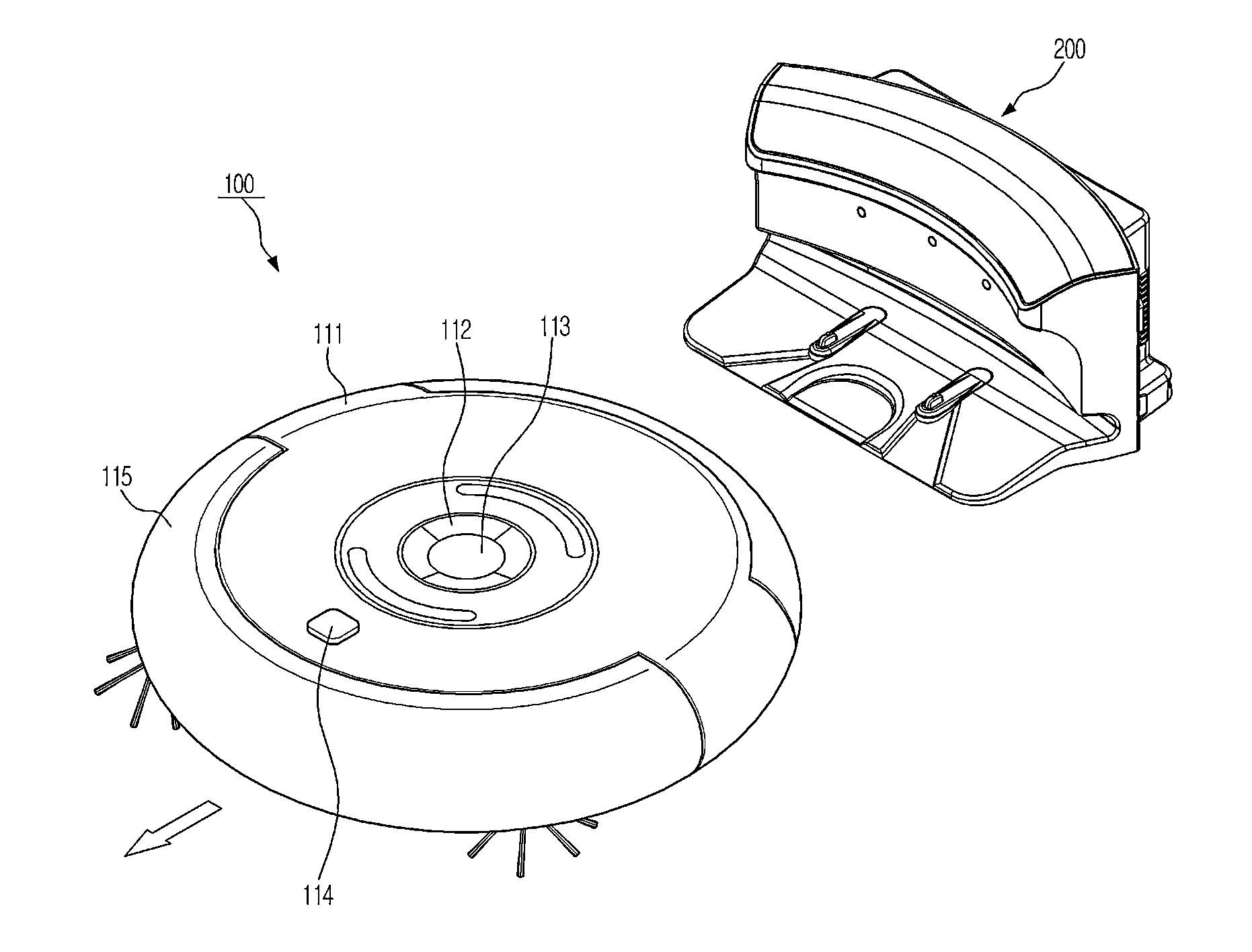
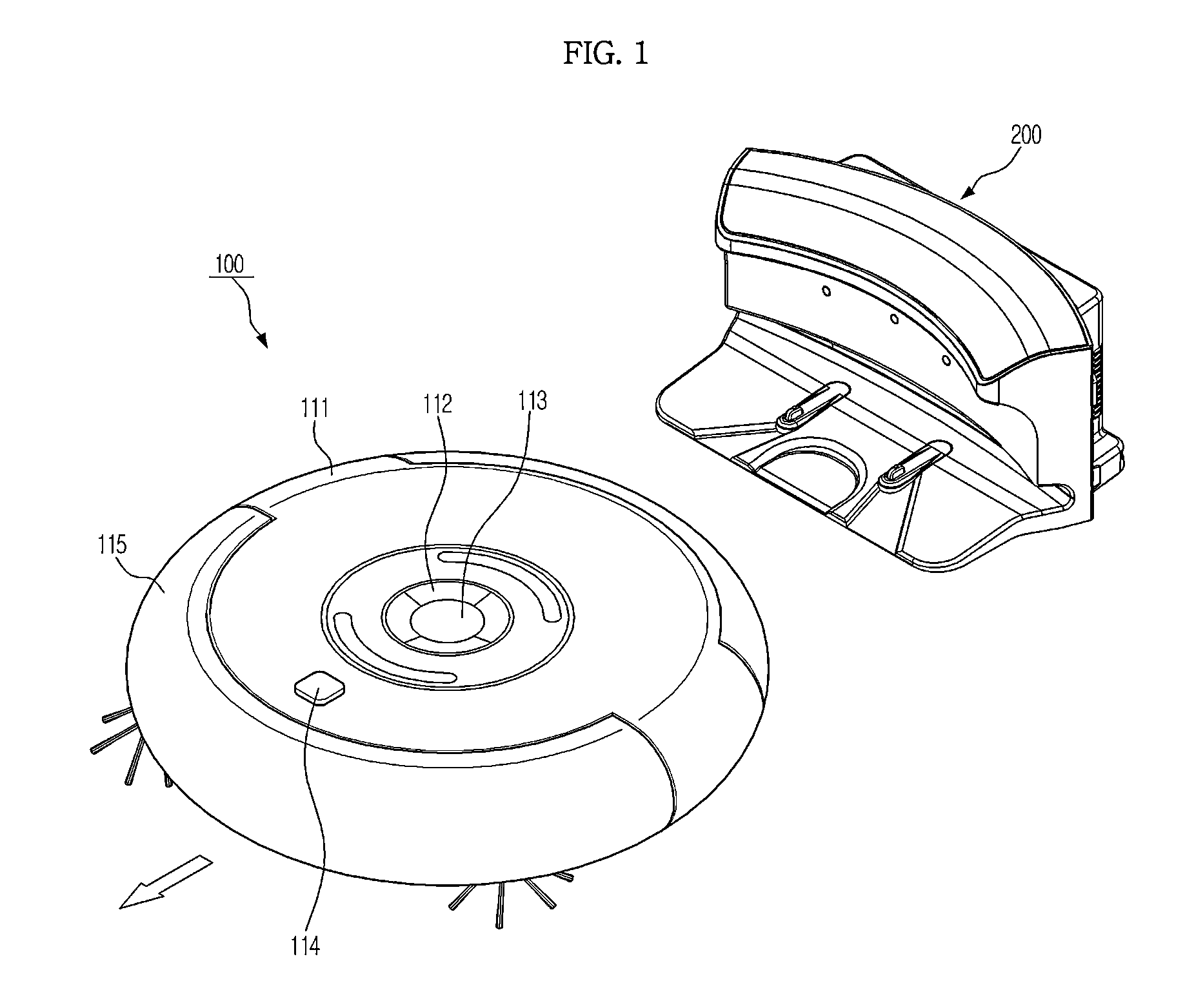
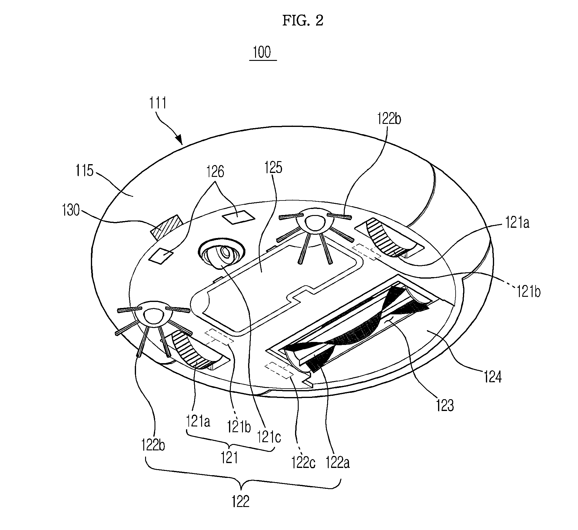
[0047]FIGS. 1 and 2 illustrate a robot cleaner 100 according to an embodiment of the present disclosure. In detail, FIG. 1 is a top perspective view of the robot cleaner 100 along with a docking station or recharging base 200, and FIG. 2 is a bottom perspective view of the robot cleaner 100.

[0048]When a cleaning command is received from a user or when the system clock reaches a scheduled time, the robot cleaner 100 autonomously travels about an area to be cleaned to suck up foreign substances such as dust present on a floor or to wipe the dust off the floor, thereby cleaning the floor. If cleaning is completed or if a battery voltage drops below a reference voltage, the robot cleaner 100 docks with a recharging base 200. When docking is completed, the robot cleaner 100 re...


PUM


Abstract

A robot cleaner includes a main body, a traveling unit installed in the main body, to move the main body, an ultrasonic sensor to emit an oscillation wave, to receive a reflection wave reflected from an object surface, and to output vibration generated by the oscillation wave and vibration generated by the reception of the reflection wave as an electrical signal, a waveform analyzer to calculate a generation time period of the electrical signal output from the ultrasonic sensor, and a controller to determine information about the object surface based on the calculated generation time period of the electrical signal, and to control movement of the traveling unit based on the information about the object surface.

Description

CROSS-REFERENCE TO RELATED APPLICATIONS[0001]This application claims the benefit of Korean Patent Application No. 10-2013-0009579, filed on Jan. 29, 2013 in the Korean Intellectual Property Office, the disclosure of which is incorporated herein by reference.BACKGROUND[0002]1. Field[0003]Embodiments of the present disclosure relate to a robot cleaner to acquire information about the surface of an object and to control operation based on the acquired information, and a control method thereof.[0004]2. Description of the Related Art[0005]Lately, with developments in electronic technology, such as computing technology, sensing technology, and communication technology, technology for automating human tasks in specific environments is rapidly advancing.[0006]Accordingly, studies into autonomous mobile devices that autonomously travel without user manipulation are being actively conducted. The autonomous mobile devices include an industrial robot, a domestic robot, a service robot, and a se...

Claims


Application Information

Patent Timeline
IPC IPC(8): B25J9/00A47L11/40
CPCA47L11/4011B25J9/0003G05D1/0255A47L9/2826A47L2201/04A47L2201/06G01N29/11G01N2291/044G01N2291/2632A47L9/28B25J13/08B25J9/16
Inventor KWON, JOONHYUNGKIM, SHINCHUN, JI WON
Owner SAMSUNG ELECTRONICS CO LTD
Learn More