Complex device and robot hand drive control apparatus

Inactive Publication Date: 2014-07-31
DENSO CORP
View PDF2 Cites 17 Cited by
  • Summary
  • Abstract
  • Description
  • Claims
  • Application Information

AI Technical Summary

Benefits of technology

[0016]In the heretofore described robot hand drive control apparatus, it is possible to calculate not only the distance to the grasp object but also the hardness of the grasp object. Because of this, it is possible to grip the grasp object at a pressure and speed in accordance with the calculated hardness. Also, as it is also possible to calculate the position and size of the grasp object, it is possible to grip the grasp object with good accuracy. Also,

Problems solved by technology

In this way, with the heretofore known grasp sensors, as it is necessary to provide the distance sensor and

Method used


Image

  • Complex device and robot hand drive control apparatus
  • Complex device and robot hand drive control apparatus
  • Complex device and robot hand drive control apparatus

Examples


Example

First Embodiment

[0032]Firstly, a description will be given of a complex device. Herein, the complex device is used when gripping and pushing an object. Furthermore, the complex device includes a grasp sensor used when grasping an object.

[0033]Herein, firstly, a description will be given of a grasp sensor.

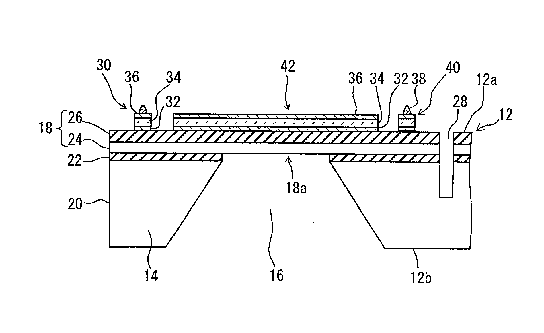
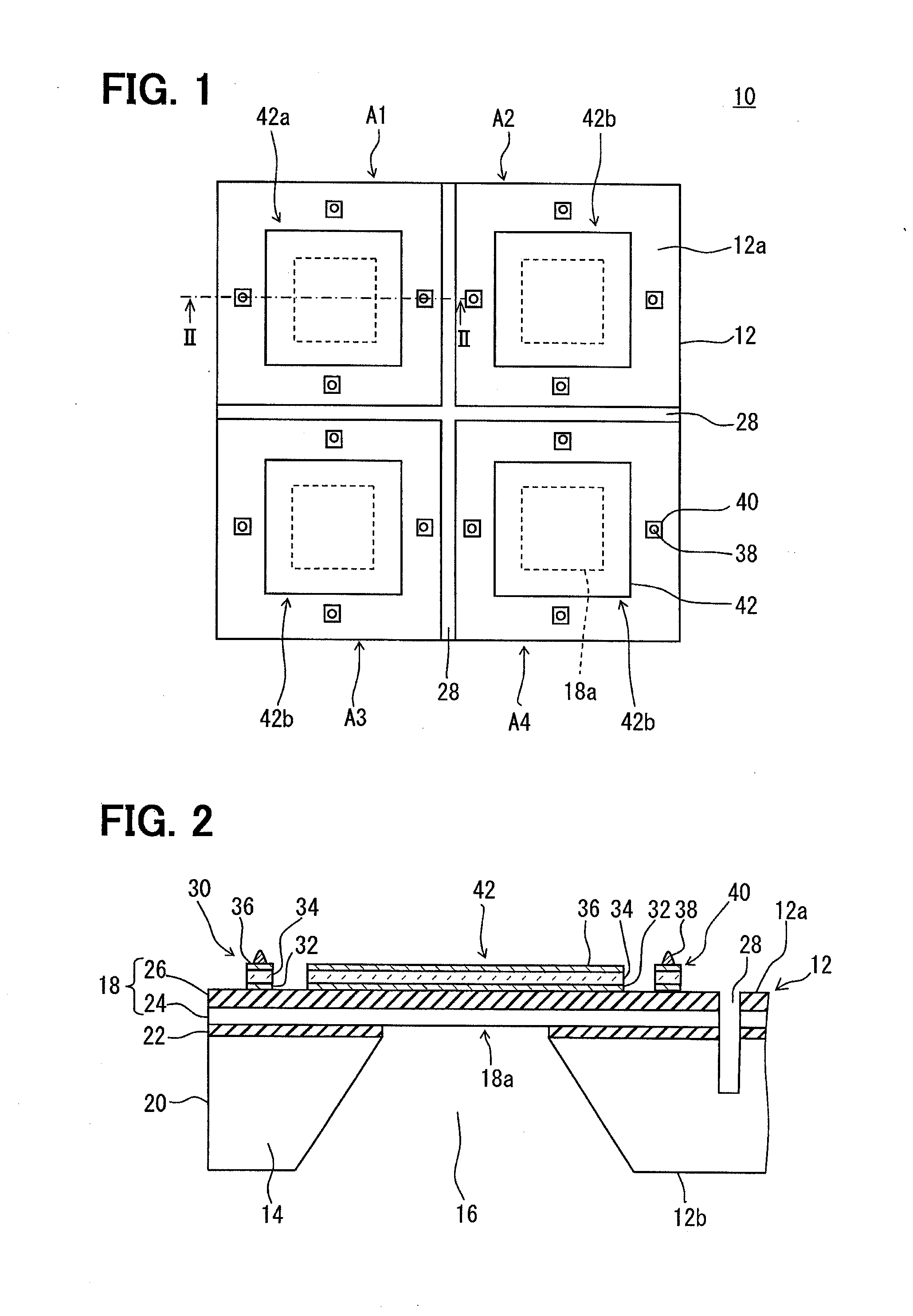
[0034]A grasp sensor 10 shown in FIGS. 1 and 2 is characterized mainly in that a piezoelectric element 30 is formed on a substrate 12, and that the piezoelectric element 30 has vertical pressure detection elements 40 and ultrasonic elements 42.

[0035]The substrate 12 has a thick portion 14, a cavity 16 surrounded by the thick portion in the horizontal direction, and a membrane 18 formed on the thick portion 14 so as to bridge the cavity 16. Further, a portion of the membrane 18 bridging the cavity 16 is made a thin-walled portion 18a thinner than a portion of the substrate 12 in which the thick portion 14 is formed, and the thin-walled portion 18a is provided so as to be deformable.

[...

Example

Modification Example

[0072]The heretofore described embodiment has shown an example of the cavities 16 formed from the rear surface 12B side of the substrate 12. However, the cavities 16 may be formed from the one surface 12a side of the substrate 12.

[0073]The disposition of the piezoelectric elements 30 (the disposition of the vertical pressure detection elements 40 and ultrasonic elements 42) in the grasp sensor 10 is not limited to the heretofore described example. For example, the heretofore described embodiment has shown an example wherein the grasp sensor 10 has one transmitting and receiving element 42a and three receiving elements 42b as the ultrasonic elements 42. However, the grasp sensor 10 has only to have at least one ultrasonic element 42 used for at least one of ultrasonic transmission or ultrasonic reception. For example, a configuration may be adopted wherein the grasp sensor 10 has one ultrasonic element 42 used for only ultrasonic transmission and a plurality of re...

Example

Second Embodiment

[0078]In this embodiment, a description of the same portions as those of the grasp sensor 10 and robot hand drive control apparatus 50 shown in the heretofore described embodiment will be omitted. The first embodiment has shown an example wherein the grasp sensor 10 has only the vertical pressure detection elements 40 as a tactile sensor.

[0079]As opposed to this, this embodiment is characterized in that the grasp sensor 10 also includes shear force detection elements 72, as well as the vertical pressure detection elements 40, as a tactile sensor. Also, this embodiment is characterized in that the robot hand drive control apparatus 50 feedback controls the grasp condition of the robot hand 200 using a shear force detected by the shear force detection elements 72, as well as the heretofore described vertical pressure.

[0080]As shown in FIGS. 7 and 8, the grasp sensor 10 according to this embodiment includes an ultrasonic element 42 of the same form as in the first embo...


PUM


Abstract

A complex device includes: a substrate having a thick portion, a cavity and a membrane for bridging the cavity; and multiple piezoelectric elements having a lower electrode, a piezoelectric film and an upper electrode. A part of the piezoelectric elements has a projecting portion arranged on the upper electrode. The part of piezoelectric elements (30) provides a vertical pressure detection element. The piezoelectric elements further have an ultrasonic element other than the vertical pressure detection element. The ultrasonic element is arranged over at least the cavity of the substrate in a horizontal direction.

Description

CROSS REFERENCE TO RELATED APPLICATION[0001]This application is based on Japanese Patent Application No. 2011-240522 filed on Nov. 1, 2011, the disclosure of which is incorporated herein by reference.TECHNICAL FIELD[0002]The present disclosure relates to a complex device and a robot hand drive control apparatus including the complex device.BACKGROUND ART[0003]As a grasp sensor used when a robot hand or the like grasps a grasp object, for example, a sensor including a distance sensor and a tactile sensor is known, as shown in Patent Literature No. 1.[0004]Also, as the tactile sensor, a sensor of the form shown in Patent Literature No. 2 is known. The tactile sensor shown in Patent Literature No. 2 has, on a substrate, a stacked portion including a first layer and second layer disposed in the order from the substrate side, a raised portion formed by bending the first layer and second layer toward the second layer side, and a detection device for detecting a deformation of the raised p...

Claims


Application Information

Patent Timeline
IPC IPC(8): B25J9/16G01L1/16B06B1/06
CPCB25J9/1612G01L1/16B06B1/0674B25J13/082G01B17/00G01L1/162G01L1/255G01L5/226
Inventor SUGIURA, MAKIKOHIGUCHI, HIROFUMI
Owner DENSO CORP
Why Eureka
Try Eureka