Agricultural harvesting machine

a harvesting machine and agri-industrial technology, applied in the direction of mowers, cutters, picking devices, etc., can solve the problems of increasing the energy consumption of driving the chopping assembly, reducing the quality of chopping, and chopping knives, so as to reduce oscillations, reduce noise, and increase rotational speed

Active Publication Date: 2014-08-07
CLAAS SELBSTFAHRENDE ERNTEMASCHINEN GMBH
View PDF20 Cites 59 Cited by
  • Summary
  • Abstract
  • Description
  • Claims
  • Application Information

AI Technical Summary

Benefits of technology

[0009]To that end, the present invention provides an agricultural harvesting machine of the aforementioned type, in which maintenance processes to be carried out on the running chopper drum is better implemented and, for various configurations of the chopping assembly.
[0011]The rotational speed of the drum is therefore influenced by a control device, at least during the maintenance procedure, thereby making it possible to implement the maintenance procedure in a suitable manner with consideration for the properties of the particular drum that is used. Influencing the rotational speed results in advantages for various maintenance procedures.
[0013]According to an embodiment, a property of the drum can be the natural frequencies thereof. The advantage of accounting for the natural frequencies of the drum is that the drum rotational speed can be set in gaps between the natural frequencies during the maintenance procedure, thereby substantially reducing disadvantageous vibrations resulting from natural oscillations.
[0016]Such a tool can be a sharpening device for the knives of the drum. Advantageously, the rotational speed of the drum is then selected such that contact interruptions between the sharpening stone and the knives, which may result between successive knives due to knife gaps, are so brief that the sharpening stone is prevented from abruptly dropping radially into these knife gaps. This is achieved, in particular, in that a higher rotational speed is selected for a drum equipped with fewer knives than that selected for a drum equipped with a relatively greater number of knives. Due to the rotational speed adaptation that is provided, the sharpening procedure takes place with markedly reduced oscillations, in particular for drums equipped with fewer knives. In addition to reduced oscillations and, therefore, reduced noise, the rotational speed adaptation described also yields an improved sharpening result which is more uniform.
[0017]Within the scope of the use of the rotational speed control for a sharpening procedure, it can also be advantageously provided that the rotational speed of the drum selected for the sharpening procedure is also adapted depending on the state of use of the knives. Therefore, a different rotational speed could be utilized during the sharpening of new knives (unused), for example, than during the sharpening of knives that have already been worn down. Since worn knives are typically shorter than new knives, a drum equipped with worn knives has longer knife gaps. Therefore, such a drum could be advantageously sharpened at a higher rotational speed in order to thereby compensate for the longer knife gaps and prevent the disadvantageous radial abrupt dropping of the sharpening stone.
[0018]As an alternative or in addition thereto, the tool can be a device for adjusting the distance of the shear bar from the drum. Such shear bar adjustment devices are typically based on the technique of slowly and incrementally moving the shear bar toward the rotating drum until oscillation sensors (so-called “knock sensors”) detect contact by the knives with the shear bar. Since the measurement signals of the knock sensors are usually subject to strong noise, the evaluation of the signals, which is required for the adjustment process, is made difficult. If different drums and / or drums that are equipped with knives in different manners are used, it becomes even more difficult to match the measurement signals to knife contacts that have occurred. In order to simplify the signal evaluation, it is therefore advantageous to select the rotational speed of the drum during the procedure for adjusting the shear bar such that the knock frequency that can be detected at the shear bar is approximately identical for different knife-installation states and / or drum types. Thus, the drum rotates twice as rapidly when equipped with half as many knives as compared to the total number of knives in order to ensure that the knock sensors detect the same impact frequency in each case. The evaluation of the signals can then also be carried out for different knife-installation states of drums, in the same manner in each case, and in particular using the same data evaluation program.

Problems solved by technology

The reason therefor is that the cutting process to which the incoming crop is continuously subjected induces wear on the chopping knives and on the shear bar of the chopping assembly.
If chopping is performed using blunt knives and / or with a shear bar that is imprecisely adjusted, for whatever reason, this in turn results in reduced chopping quality and increased energy consumption for driving the chopping assembly.
In respect of sharpening processes to be carried out, as the distance between successive knives increases, whether due to the design of the chopper drum and / or due to the knife-installation state, the risk also increases that the sharpening stone, which is radially preloaded against the chopper drum, will abruptly drop into the intermediate spaces (gaps) between the knives.
This abrupt drop induces strong oscillations, which are expressed as loud, audible, unpleasant noises and also result in premature wear at least of the knives and the sharpening device.
Due to the sensor system used in this adjustment process and due to other ambient conditions, the knock-sensor signals to be evaluated contain a large noise component.
In particular, when chopper drums are equipped with different numbers of knives and / or when different types of cutting cylinders are used, it is difficult for evaluation electronics that are used to detect individual knives from among low-voltage, noisy signals.
This problem intensifies in practical applications since an increasing bandwidth of drums and numbers of knives is used and the knock sensors must therefore detect knocking that is triggered with very different timing.

Method used


Image

  • Agricultural harvesting machine
  • Agricultural harvesting machine
  • Agricultural harvesting machine

Examples


Embodiment Construction

[0024]The following is a detailed description of example embodiments of the invention depicted in the accompanying drawings. The example embodiments are presented in such detail as to clearly communicate the invention and are designed to make such embodiments obvious to a person of ordinary skill in the art. However, the amount of detail offered is not intended to limit the anticipated variations of embodiments; on the contrary, the intention is to cover all modifications, equivalents, and alternatives falling within the spirit and scope of the present invention, as defined by the appended claims.

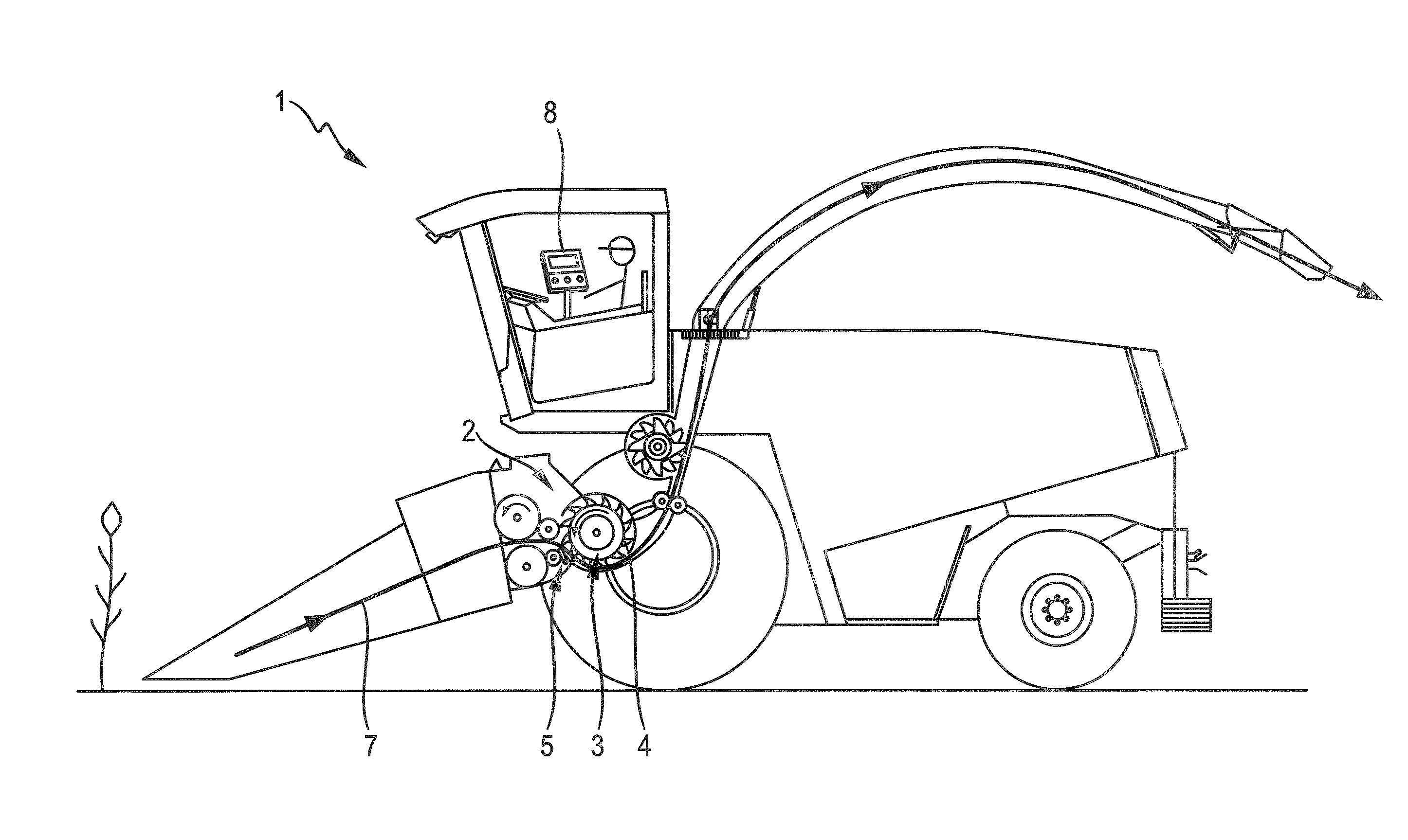
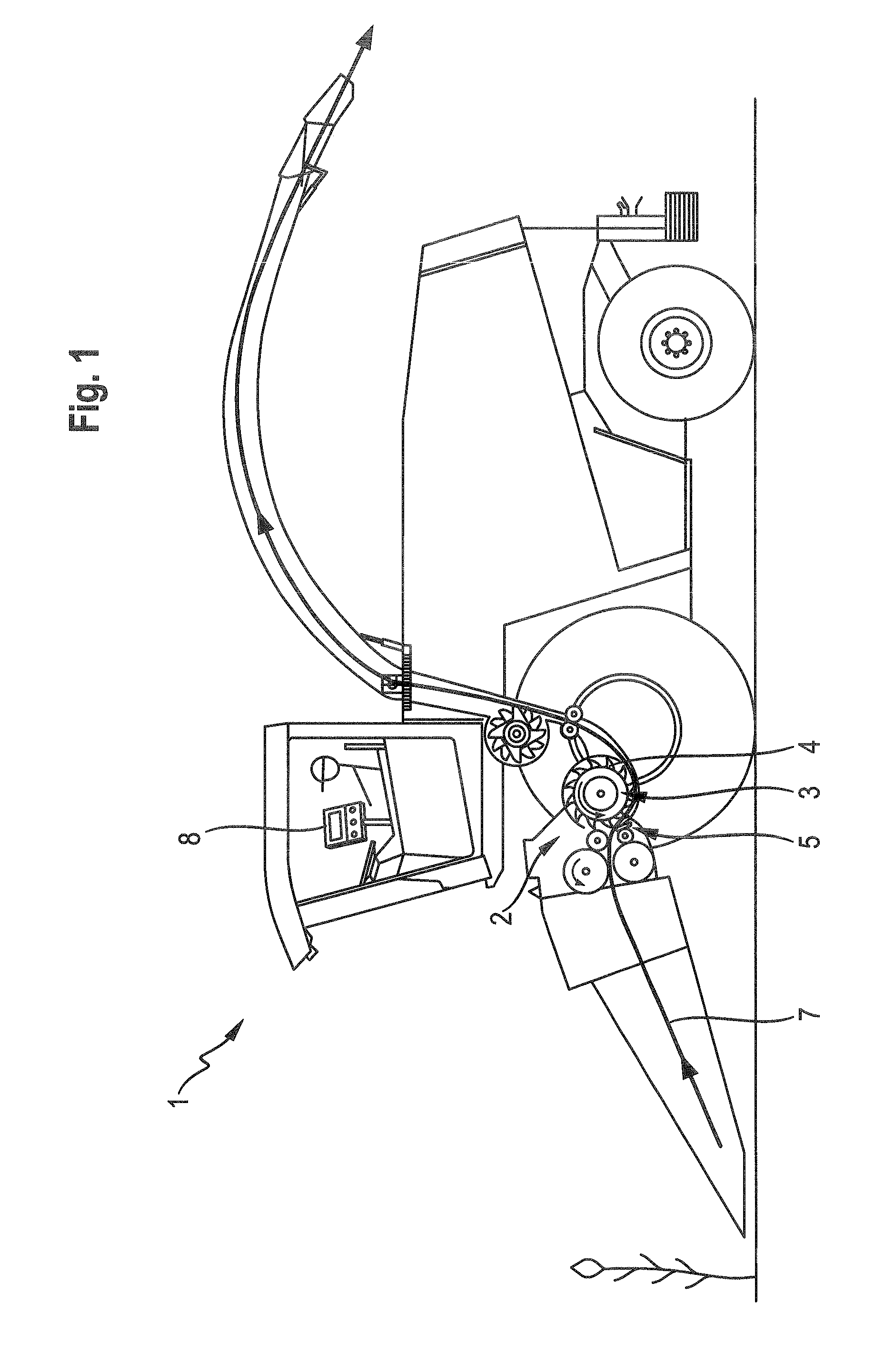
[0025]FIG. 1 shows an agricultural harvesting machine in the form of a self-propelled forage harvester 1. The forage harvester 1 has typical features of a forage harvester, which are known per se and are therefore not explained in detail herein. During the harvesting operation, the forage harvester 1 is used to comminute (“chop”) picked-up crop 7, which is fed to a chopping assembly 2 in th...


PUM


Abstract

An agricultural harvesting machine embodying a forage harvester includes a comminution assembly with a drum equipped with a plurality of knives. The drum is set into rotation opposite a stationary shear bar in order to comminute crop fed in a region of a cutting gap formed by knives and the shear bar during the harvesting operation. A device controls a rotational speed (n) of the drum at least during a maintenance procedure of the comminution assembly, depending on a property of the drum.

Description

CROSS-REFERENCE TO A RELATED APPLICATION[0001]The invention described and claimed hereinbelow is also described in German Priority Document DE 10 2013 101183.7, filed on Feb. 7, 2013. The German Priority Document, the subject matter of which is incorporated herein by reference, provides the basis for a claim of priority of invention under 35 U.S.C. 119(a)-(d).BACKGROUND OF THE INVENTION[0002]The invention relates to an agricultural harvesting machine (e.g., a forage harvester) configured with a comminution assembly having a drum equipped with a plurality of knives that is set into rotation opposite a stationary shear bar in order to comminute crop fed in the region of a cutting gap formed by knives and shear bar during the harvesting operation, and more particularly relates to such a machine that includes a device for controlling the rotational speed (n) of the drum at least during a maintenance procedure of the comminution assembly depending on a property of the drum.[0003]During o...

Claims


Application Information

Patent Timeline
Patent Type & Authority Applications(United States)
IPC IPC(8): A01D43/08
CPCA01D43/08A01F29/14A01D43/085A01F29/22
Inventor POLLKLAS, MANFRED
Owner CLAAS SELBSTFAHRENDE ERNTEMASCHINEN GMBH
Why Eureka
Try Eureka