Valve timing adjustment system

Active Publication Date: 2014-08-07
AISIN SEIKI KK
View PDF59 Cites 3 Cited by
  • Summary
  • Abstract
  • Description
  • Claims
  • Application Information

AI Technical Summary

Benefits of technology

[0025]Of course, the two methods for calculating the degree of degradation may be combined. If the degree of degradation is derived from the travel distance of the vehicle and/or the amount of time that has passed since the last oil change and a map that derives a change instruction value for changing the temporal responsiven

Problems solved by technology

However, because the response speed in the locking operation/lock release operation control is changed after it has been determined that locking or a lock release has been requested, there is a problem in that proper valve timing control cannot be carried out if the timing of the determi

Method used


Image

  • Valve timing adjustment system
  • Valve timing adjustment system
  • Valve timing adjustment system

Examples


first embodiment

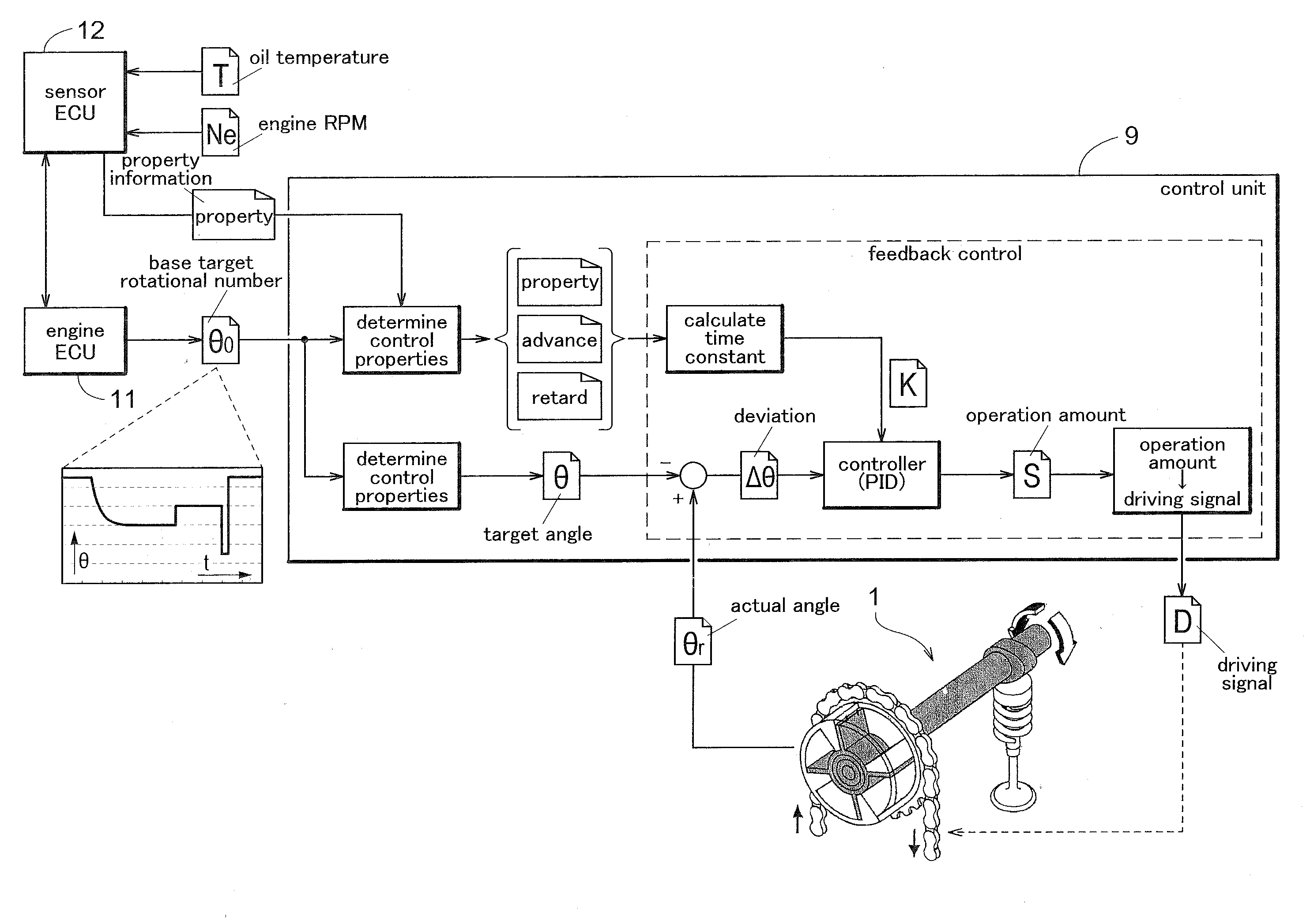
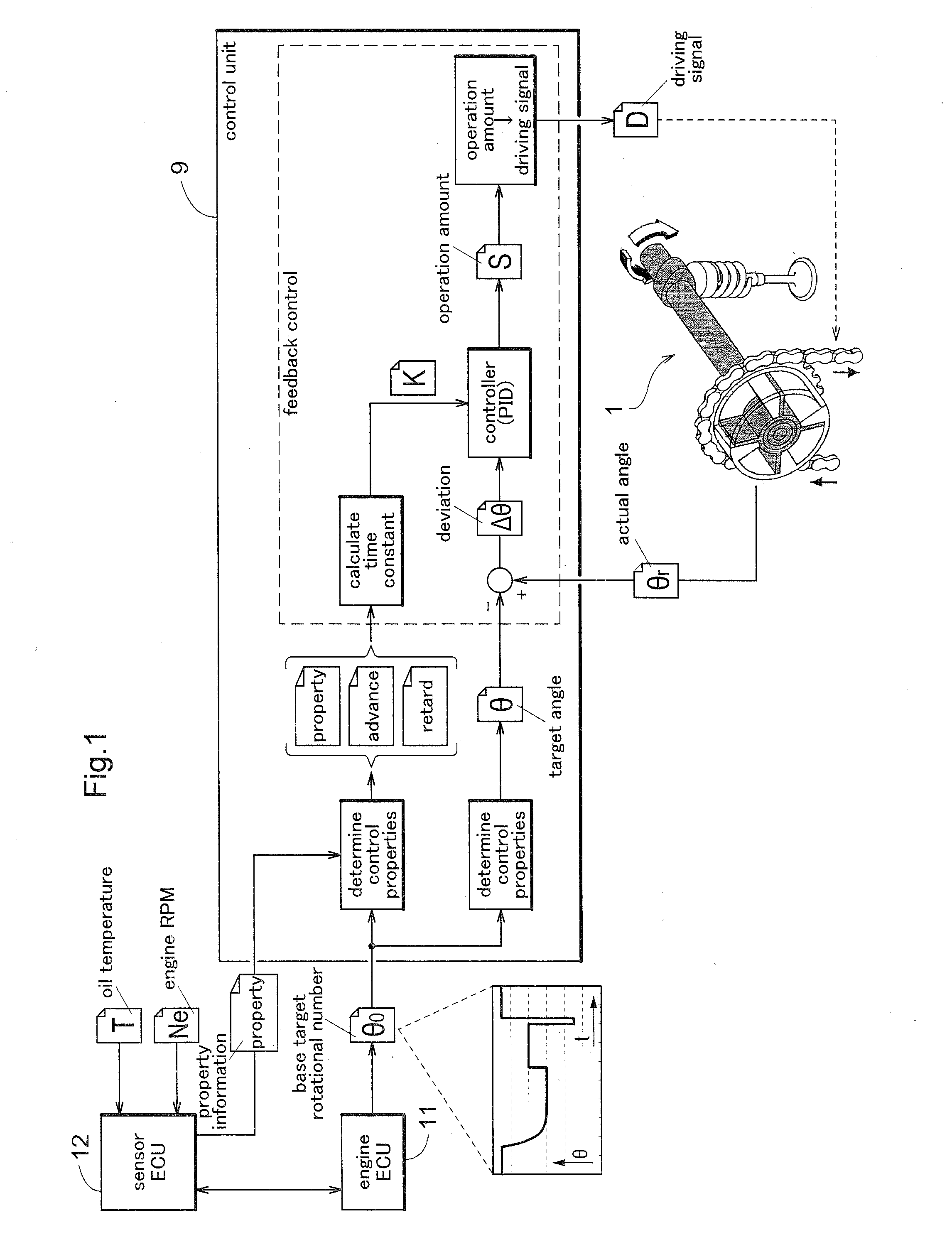
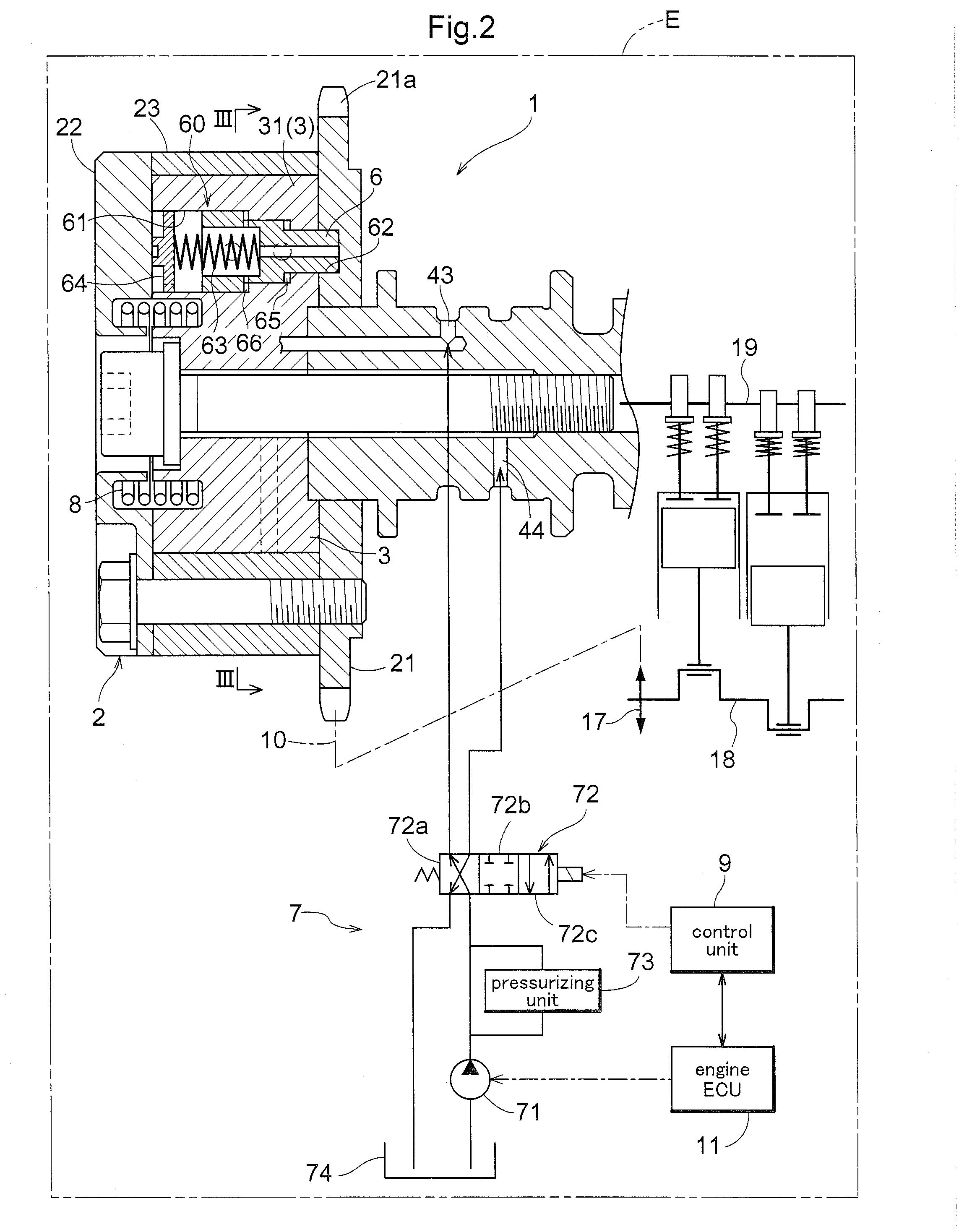
[0056]Before describing a first embodiment of a valve timing adjustment system according to the present invention, an overall description of the invention will be given using the schematic diagram in FIG. 1. This system includes a valve timing adjustment mechanism (“VVT mechanism” hereinafter) 1 that is controlled by a control unit 9. Although specific descriptions will be given later, the VVT mechanism 1 includes a displacement mechanism unit that displaces the rotational phase of a camshaft 19 relative to a crankshaft 18 of an internal combustion engine (also referred to simply as an engine) E in an advance direction D1 or a retard direction D2, and a locking mechanism unit 60 (not shown in FIG. 1) that locks the rotational phase at an intermediate locked phase positioned within a displacement range of the rotational phase. The displacement mechanism unit and the locking mechanism unit 60 are operated by a hydraulic control valve 72 (not shown in FIG. 1) whose driving is controlle...

second embodiment

[0154]Before describing a second embodiment of a valve timing adjustment system according to the present invention, an overall description of the invention will be given using the schematic diagram in FIG. 18. In the following descriptions of the present embodiment, areas having the same configurations as those in the first embodiment will be assigned the same reference signs, and descriptions of the same configurations will be omitted. This system includes the VVT mechanism 1 that is controlled by a control unit 90. Although specific descriptions will be given later, the VVT mechanism 1 includes the displacement mechanism unit that displaces the rotational phase of the camshaft 19 relative to the crankshaft 18 of the engine E in the advance direction D1 or the retard direction D2, and the locking mechanism unit 60 (not shown in FIG. 18) that locks the rotational phase at an intermediate locked phase positioned within a displacement range of the rotational phase. The displacement me...


PUM


Abstract

Provided is a valve timing adjustment system having improved control for achieving a target rotational phase. The valve timing adjustment system includes: a displacement mechanism unit that displaces a rotational phase of a camshaft relative to a crankshaft of an internal combustion engine; a locking mechanism unit that locks the rotational phase at an intermediate locked phase positioned within a displacement range of the rotational phase; a hydraulic pathway that hydraulically drives the displacement mechanism unit and the locking mechanism unit; and a control unit including a control system that controls operations of the hydraulic control valve. The control unit changes a temporal responsiveness of the control system based on a displacement force that displaces the rotational phase.

Description

TECHNICAL FIELD[0001]The present invention relates to valve timing adjustment systems that control the relative rotational phase of a driven-side rotating member relative to a driving-side rotating member that rotates in synchronization with a crankshaft in an internal combustion engine.BACKGROUND ART[0002]A valve timing control device is known that includes a hydraulic lock mechanism configured of a locking recess formed in a driven-side rotating member and a locking member capable of extending into / retracting from the locking recess, in order to hold a relative rotational phase (called simply a “rotational phase” hereinafter) of the driven-side rotating member relative to a driving-side rotating member in a predetermined intermediate rotational phase (a locked rotational phase or locked position). Here, the locking member being inserted into the locking recess will be referred to as locking or a locking operation, whereas the locking member retracting from the locking recess will ...

Claims


Application Information

Patent Timeline
IPC IPC(8): F01L1/356F01L1/344
CPCF01L1/356F01L2001/34423F01L1/3442F01L2001/0476F01L2001/3443F01L2001/34466F01L2001/34469F01L2001/34476F01L2001/34483F01L2250/02F01L2800/00F01L2800/05F02D13/0219Y02T10/12
Inventor KOKUBO, SATOSHIKAKUDA, YUJIIKEDA, KENJIOHTA, YUUKIKOBAYASHI, MASAKI
Owner AISIN SEIKI KK
Why Eureka
Try Eureka