
Traveling wave antenna plasma source

A technology of plasma source and traveling wave antenna, applied in the field of ion source, can solve the problems of time-consuming, complicated process, inconvenient operation, etc., and achieve the effect of fast response, easy to use, and simple structure

Active Publication Date: 2021-08-24
UNIV OF SCI & TECH OF CHINA
View PDF4 Cites 3 Cited by
  • Summary
  • Abstract
  • Description
  • Claims
  • Application Information

AI Technical Summary

Problems solved by technology

However, this method takes a long time (about 40ms), and the process is complicated and inconvenient to operate

Method used


Image

  • Traveling wave antenna plasma source
  • Traveling wave antenna plasma source
  • Traveling wave antenna plasma source

Examples


Embodiment Construction

[0042] The present invention will be described in detail below in conjunction with the accompanying drawings and embodiments.

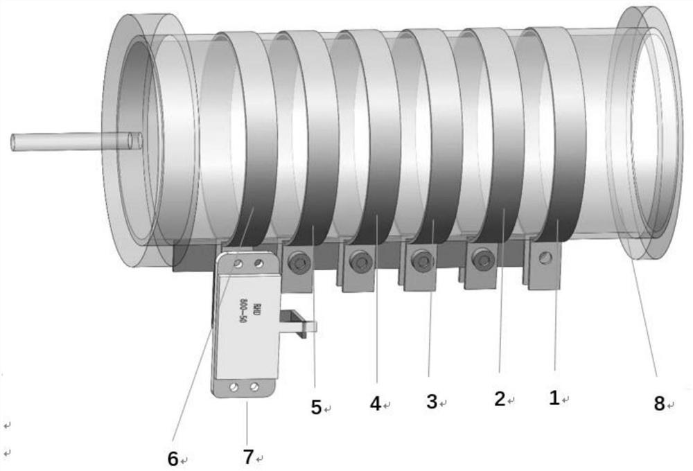
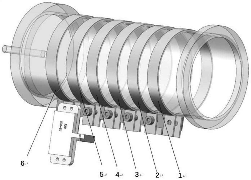
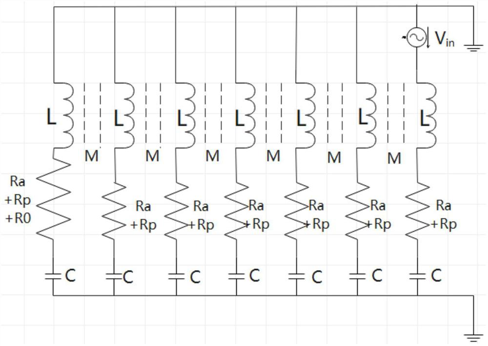
[0043] figure 1 , figure 2 The traveling-wave antenna structure independently designed for the present invention consists of six loop antennas placed outside the vacuum chamber. Among them, 1 is the feed antenna, 2-5 are four short-circuit antennas, 6 is the dummy load antenna, 7 is the 50Ω dummy load, and 8 is the quartz tube. The first antenna on the right is connected to the RF source as the power feeding end, the four antennas in the middle are short-circuited as the coupling end, and the first antenna on the left is connected to a 50Ω dummy load as the absorbing end. Such as figure 1 , label 1 represents the first antenna, which is the feed antenna; labels 2-5 are the four short-circuit antennas in the middle, which are used as coupling RF power antennas; 6 is connected to the dummy load antenna, which is used as the absorbing end. The six a...


PUM


Abstract

The invention relates to a traveling wave antenna plasma source which is composed of six loop antennas and placed outside a vacuum chamber. The first antenna at the front end is connected with a radio frequency source to serve as a power feed-in end, the four antennas in the middle are short-circuited to serve as coupling ends, and the antenna at the tail end is connected with a 50-ohm dummy load to serve as an absorption end. The radio frequency plasma source with high coupling efficiency and low reflection can be obtained, the coupling efficiency can reach 100%, and the reflection power can be reduced to zero.

Description

technical field [0001] The invention relates to a plasma source, in particular to a traveling wave antenna plasma source. Background technique [0002] Plasma is a multi-particle system composed of positive and negative ions and neutral gases, which is electrically neutral as a whole. Among them, the main purpose of high-temperature plasma research is to realize controlled nuclear fusion and solve the energy problem of human beings in the future. Therefore, it is particularly important to effectively generate plasma sources under laboratory conditions. [0003] Plasmas under current laboratory conditions are mainly generated by ionizing neutral gases. Normally, neutral gas is a non-conductive insulating medium. If two electrode pieces are placed in the gas and an appropriate voltage is applied, the gas will be broken down to generate a huge current. This gas will form a huge current when the voltage is added. The phenomenon is called gas discharge. According to the diffe...

Claims


Application Information

Patent Timeline
Patent Type & Authority Applications(China)
IPC IPC(8): H05H1/46
CPCH05H1/46
Inventor 李清朱光辉孙玄
Owner UNIV OF SCI & TECH OF CHINA
Learn More