Power system and control method thereof

a power system and control method technology, applied in the direction of power conversion systems, dc-dc conversion, instruments, etc., can solve the problems of poor affecting the efficiency and stability of the stability of the loop formed by the constant-voltage output pwm power system, etc., to reduce output current and reduce power loss. , the effect of constant output power

Active Publication Date: 2014-08-07
CHANGSHA HKC OPTOELECTRONICS CO LTD
View PDF9 Cites 3 Cited by
  • Summary
  • Abstract
  • Description
  • Claims
  • Application Information

AI Technical Summary

Benefits of technology

[0008]The technical issue to be addressed by the present invention is to provide a power system and control method thereof, able to guarantee constant output power and reduce output current so as to reduce the power loss due to thermal conversion and reduce the temperature of the power system and the supplied devices.
[0010]According to a preferred embodiment of the present invention, in response to the current detection unit detecting the current amplitude of the PWM output greater than a predefined current, the feedback signal generation unit can generate a second feedback so that the PWM power source can receive the second feedback signal from the feedback signal input terminal to reduce the current amplitude of the PWM output.
[0012]According to a preferred embodiment of the present invention, the PWM power source can increase the voltage amplitude of the PWM output to maintain constant power of the PWM output based on the second feedback signal received by the feedback signal input terminal.
[0014]According to a preferred embodiment of the present invention, the feedback signal generation unit can generate the first feedback signal based on a signal indicating the voltage amplitude of the PWM output received from the voltage detection unit.
[0015]According to a preferred embodiment of the present invention, the PWM power source can increase the current amplitude of the PWM output based on the first feedback signal received by the feedback signal input terminal.
[0025]According to a preferred embodiment of the present invention, the step of adjusting the PWM output can further comprise: increasing the current amplitude of the PWM output based on the first feedback signal.

Problems solved by technology

In known technique, the problem of the constant-voltage output PWM power system is that when the current amplitude of the PWM output increases, the efficiency and stability of the constant-voltage output PWM power system may be affected.
As a result, the stability of the loop formed by the constant-voltage output PWM power system and the load or supplied device becomes poor.

Method used


Image

  • Power system and control method thereof
  • Power system and control method thereof
  • Power system and control method thereof

Examples


Embodiment Construction

[0033]For description of the technical means and result of the present invention, the following refers to the drawings and embodiments for detailed description, wherein the same number indicates the same part. For clarity and convenience, the sizes of the elements may be adjusted to emphasize the description. The description of commonly known structures and functions may be omitted to facilitate clarity and understanding.

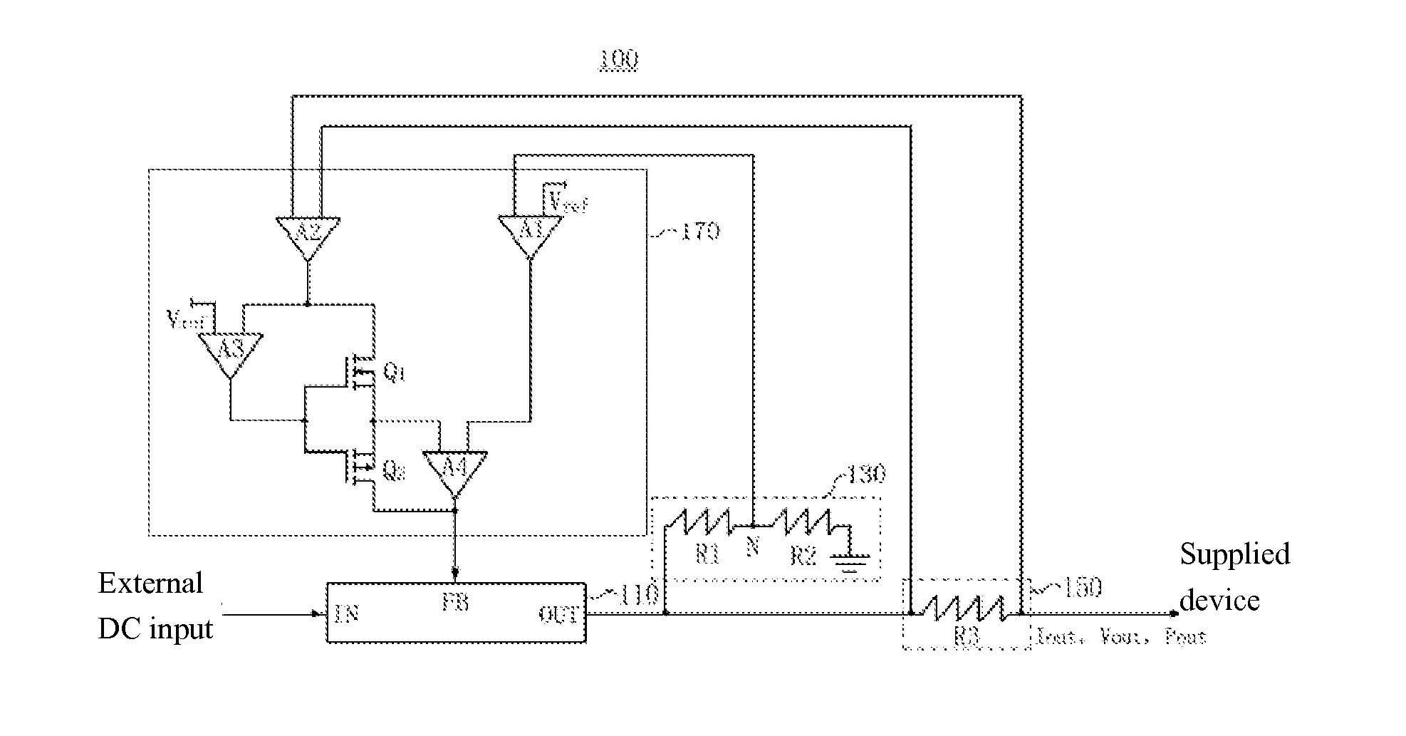
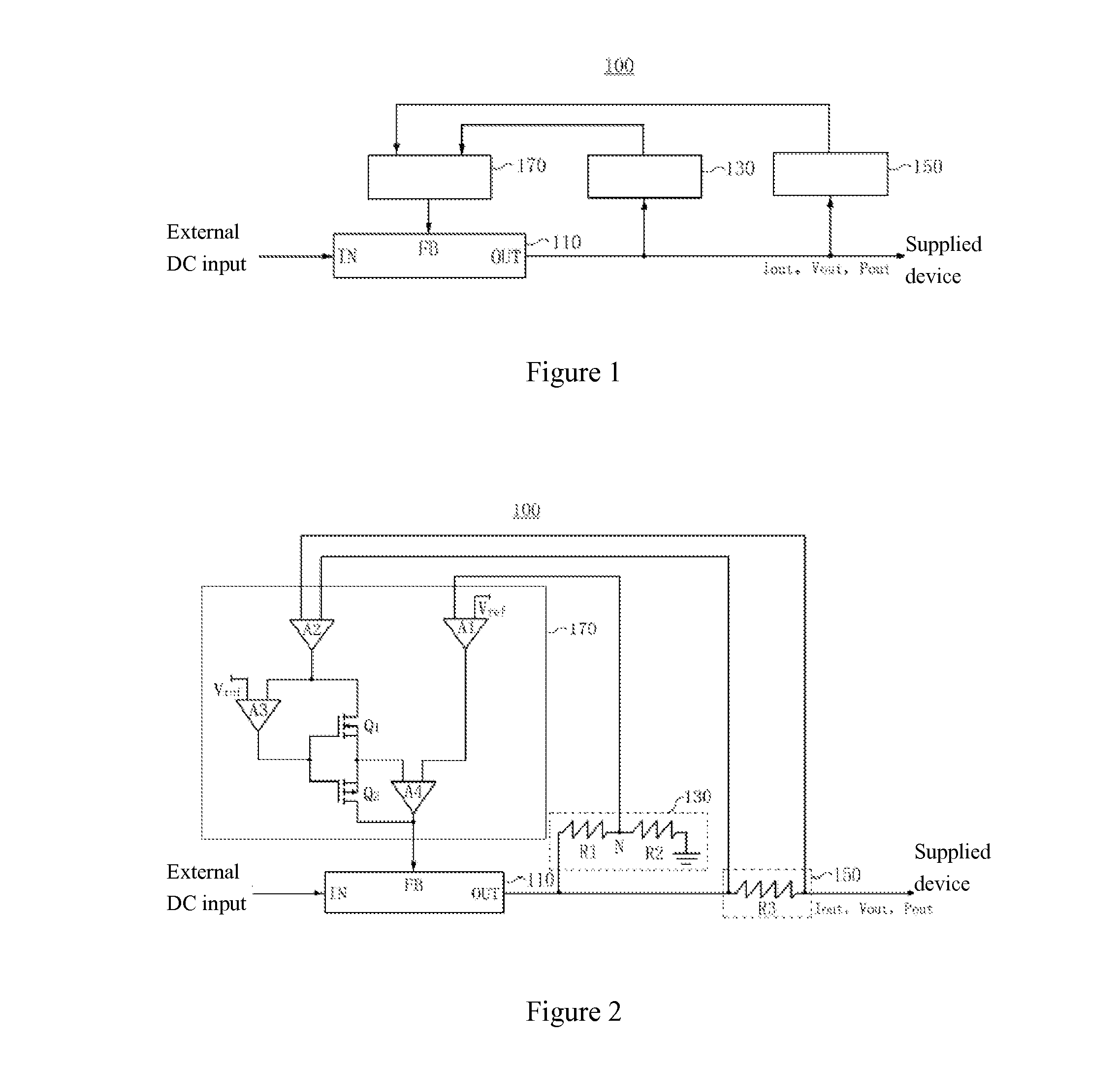
[0034]FIG. 1 is a schematic view showing the structure of a power system 100 according to an exemplary embodiment of the present invention.

[0035]Referring to FIG. 1, the power system 100 comprises: a pulse width modulation (PWM) power source 110, a voltage detection unit 130, a current detection unit 150 and a feedback signal generation unit 170.

[0036]The PWM power source 110 comprises a DC input terminal IN, a feedback signal input terminal FB and a DC output terminal OUT. The DC input terminal IN is connected to an external DC power source to receive external DC i...


PUM


Abstract

The present invention provides a power system and controlling method thereof. The power system includes: pulse width modulation (PWM) power source, voltage detection unit, current detection unit and feedback signal generation unit. PWM power source receives external DC input, performs PWM on received external DC input, and supplies PWM output obtained through PWM from the DC output terminal to a device expecting power supply. Voltage detection unit detects voltage amplitude of PWM output. Current detection unit detects current amplitude of PWM output. Feedback signal generation unit generates feedback signal and supplies generated feedback signal to PWM power source. PWM power source adjusts the voltage amplitude and current amplitude of the PWM output based on the received feedback signal.

Description

BACKGROUND OF THE INVENTION[0001]1. Field of the Invention[0002]The present invention relates to the field of power system and control method thereof, and in particular to a pulse width modulation (PWM) power system and control method thereof.[0003]2. The Related Arts[0004]The known DC-DC power supply structure comprises a constant-voltage output PWM power system able to output a voltage with constant amplitude. In such a system, when the load increases, the constant-voltage output PWM power system can adjust the PWM output so that the amplitude of the DC output current increases as the load increases.[0005]FIG. 4 is a schematic view showing the structure of a known constant-voltage output PWM power system 400.[0006]As shown in FIG. 4, the known PWM power system 400 comprises a PWM power source 410, a voltage detection unit 430 and a feedback signal generation unit 450. The PWM power source 410 receives DC input, such as, DC input voltage with 12V amplitude, from external current so...

Claims


Application Information

Patent Timeline
Patent Type & Authority Applications(United States)
IPC IPC(8): H02M3/06H02M1/00H02M1/32
CPCH02M3/06H02M1/32H02M3/156H02M1/0009
Inventor YANG, XUELIANG
Owner CHANGSHA HKC OPTOELECTRONICS CO LTD
Why Eureka
Try Eureka