
Method for magnetic resonance imaging, and magnetic resonance system

a magnetic resonance imaging and magnetic resonance technology, applied in the field of magnetic resonance, can solve the problems of unnecessary acquisition of mr signals outside the measurement region, unnecessarily prolonging the entire time period that is required to implement the measurement sequence, and reducing the overall measurement duration. , to achieve the effect of reducing the signal contribution of the transverse magnetization

Active Publication Date: 2014-08-07
SIEMENS HEALTHCARE GMBH
View PDF7 Cites 9 Cited by
  • Summary
  • Abstract
  • Description
  • Claims
  • Application Information

AI Technical Summary

Benefits of technology

This patent is about a magnetic resonance imaging (MRI) system that uses an SSFP (Simultaneous Acquisition of Spin Frequency) measurement sequence to image a specific region of an examined person. The system includes an RF pulse to excite the transverse magnetization in that region and in the outer region that surrounds it. To reduce signal interference from the outer region, the system also uses a preparation sequence that includes a multidimensional, spatially selective RF pulse to act on the transverse magnetization in that region. The technical effect is to improve the signal-to-noise ratio and decrease the measurement duration.

Problems solved by technology

However, the unnecessary acquisition of MR signals outside of the measurement region can unnecessarily extend the entire time period that is required to implement the measurement sequence (measurement duration).
However, the number of scanning points in the imaging can be limited, and the overall measurement duration thus can be reduced.
However, physiological restrictions can limit or preclude the use of such multidimensional, spatially selective RF pulses.
For instance, in cardiac imaging the time period required to implement the RF pulse can be severely limited due to heart movement, etc.

Method used


Image

  • Method for magnetic resonance imaging, and magnetic resonance system
  • Method for magnetic resonance imaging, and magnetic resonance system
  • Method for magnetic resonance imaging, and magnetic resonance system

Examples


Embodiment Construction

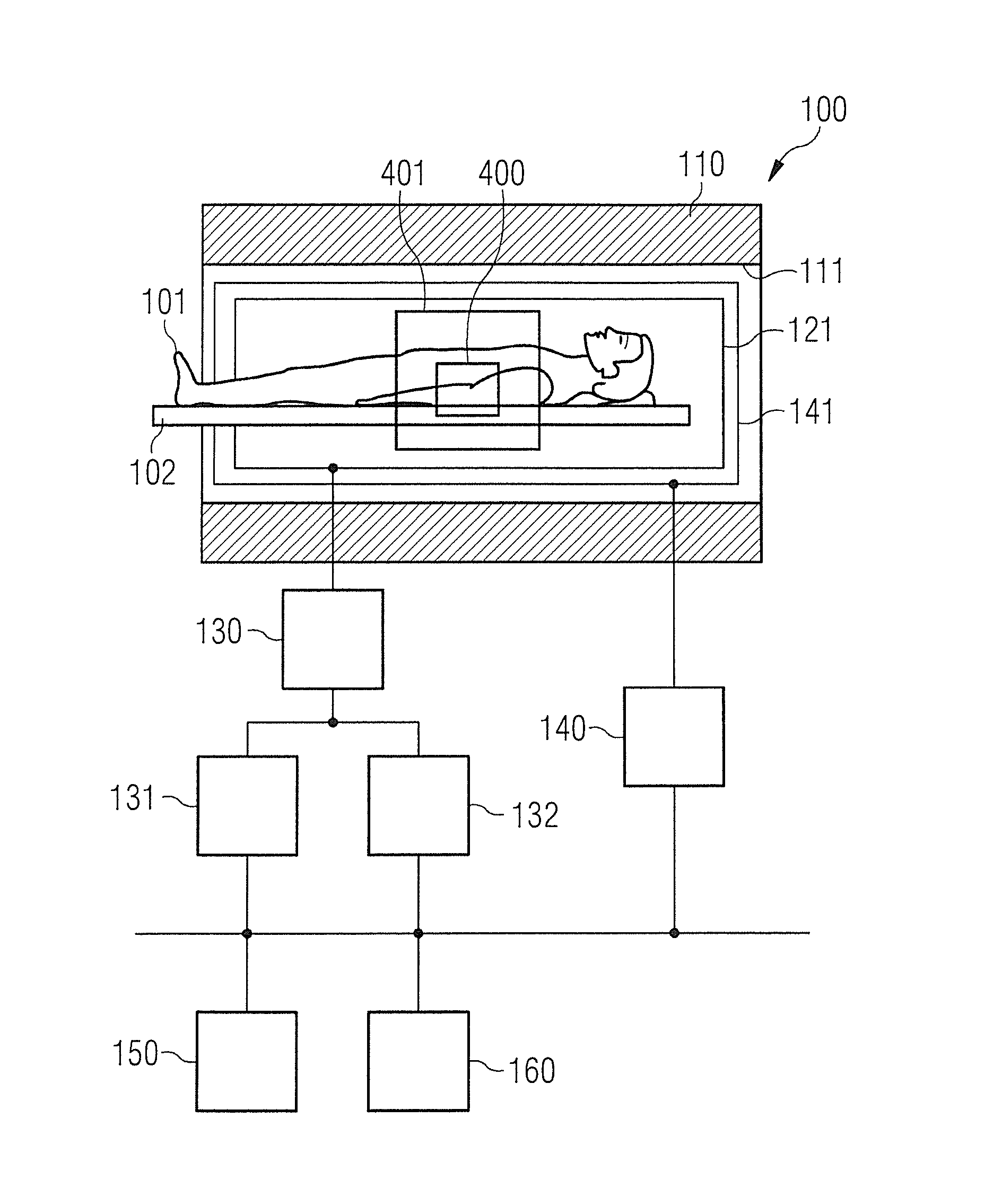
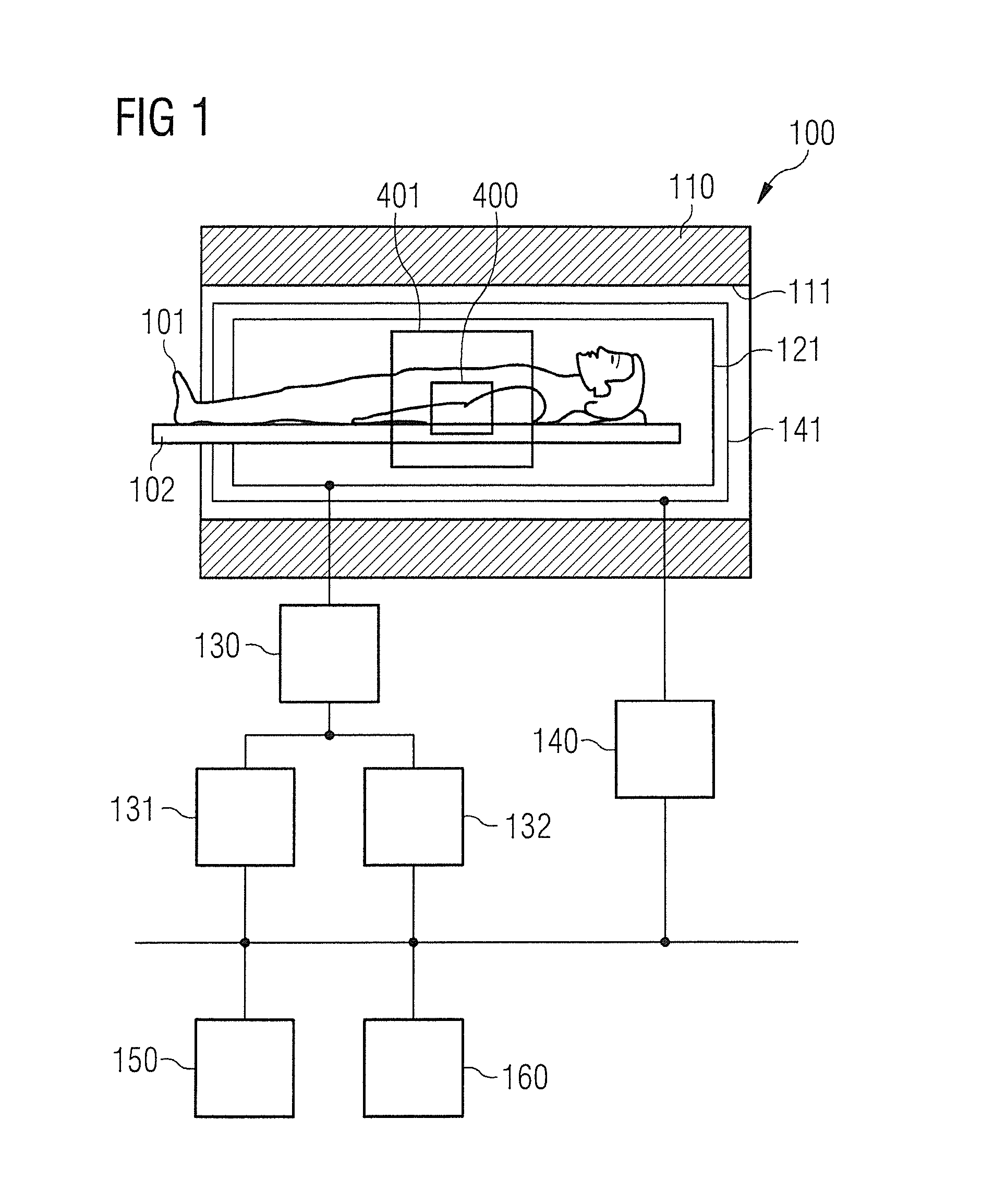
[0062]In FIG. 1, an MR system 100 is shown that is designed to implement techniques, methods and steps according to the invention. The MR system 100 has a magnet 110 that defines a tube 111. The magnet 110 generates a basic magnetic field parallel to its longitudinal axis. An examination subject—here an examined person 101—on a bed table 102 can be slid into the magnet 110. The MR system 100 furthermore has a gradient system 140 to generate gradient fields that are used for MR imaging and for spatial coding of acquired raw data. The gradient system 140 typically includes at least three separately controllable and gradient coils 141 that are positioned in a well-defined manner relative to one another. The gradient coils 141 enable gradient fields to be applied and switched along defined spatial directions (gradient axes). The corresponding gradient coils 141 are also designated as channels of the gradient system 140. For example, the channels can define a frequency coding, a readout ...


PUM


Abstract

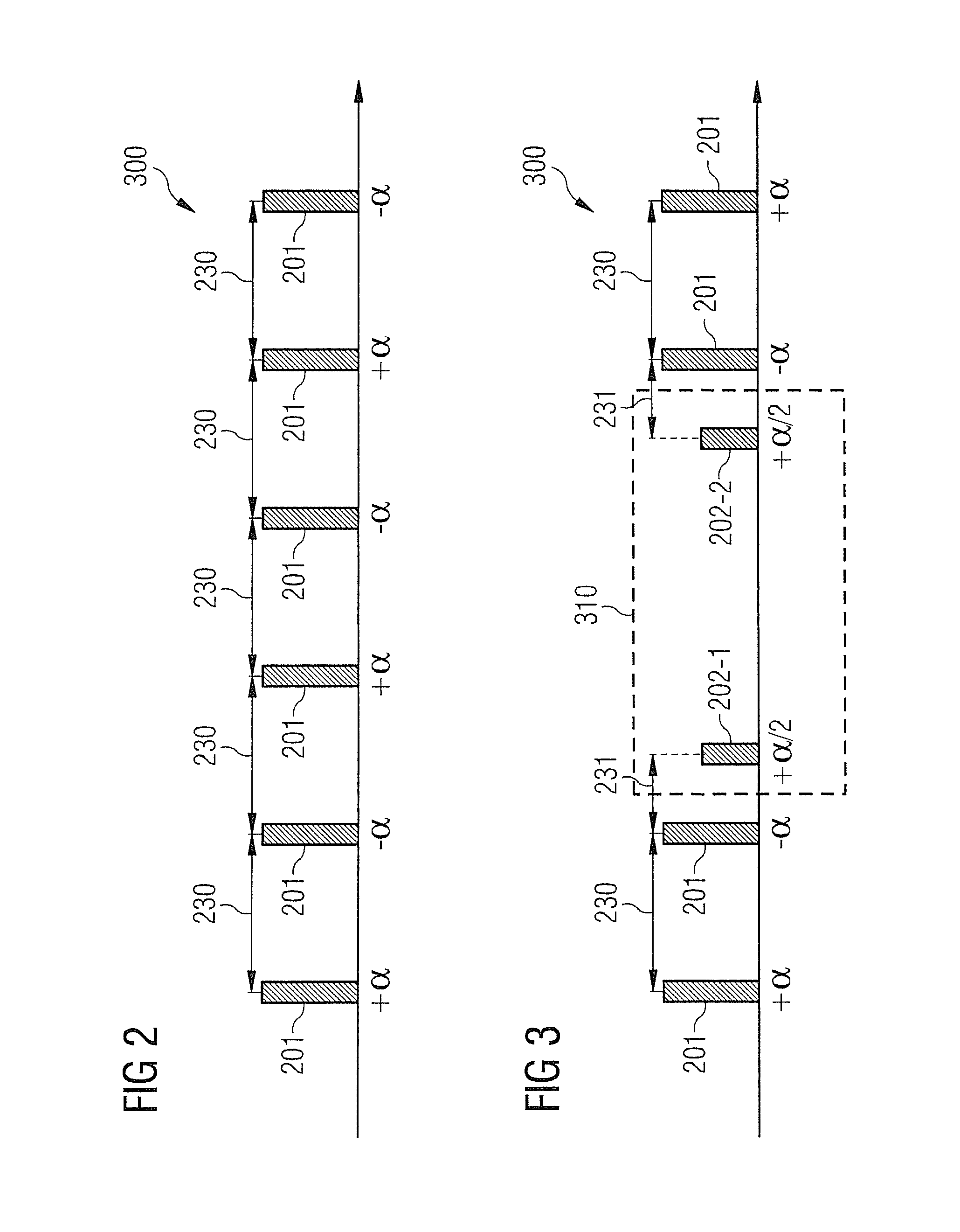
In magnetic resonance imaging using a measurement sequence of the “free precession of transverse magnetization in the steady state”-type i.e., an SSFP measurement sequence, during the SSFP measurement sequence, the implementation of a preparation sequence takes place to reduce a signal contribution of the transverse magnetization in an outer region surrounding a measurement region in the MR imaging. The implementation of the preparation sequence includes the radiation of a multidimensional, spatially selective RF pulse that acts in a spatially selective manner on the transverse magnetization in the outer region. Saturation of the transverse magnetization and / or dephasing of the transverse magnetization in the outer region can be achieved by the multidimensional, spatially selective RF pulse.

Description

BACKGROUND OF THE INVENTION[0001]1. Field of the Invention[0002]The present invention concerns a method for magnetic resonance imaging with a measurement sequence of the “free precession of transverse magnetization in the steady state”-type—an SSFP measurement sequence—and a magnetic resonance system for implementing such a method. In particular, the invention concerns measurement sequences that include the radiation of a multidimensional, spatially selective radio-frequency pulse.[0003]2. Description of the Prior Art[0004]Magnetic resonance (MR) tomography is an imaging method that enables the acquisition of two-dimensional or three-dimensional image data sets that can depict structures inside an examined person with high resolution. In MR imaging, the magnetic moments of protons in an examination subject are aligned in a basic magnetic field so that a macroscopic magnetization arises along a longitudinal direction. This is subsequently deflected (excitation) out of the steady stat...

Claims


Application Information

Patent Timeline
Patent Type & Authority Applications(United States)
IPC IPC(8): G01R33/561G01R33/483
CPCG01R33/4836G01R33/561G01R33/4838G01R33/5613
Inventor FAUTZ, HANS-PETER
Owner SIEMENS HEALTHCARE GMBH
Learn More