Producing or Dispensing Liquid Products

a technology of liquid products and liquid products, which is applied in the direction of carburettors, lighting and heating apparatus, mixing methods, etc., can solve the problems of reducing the carbonation level of the liquid product, and reducing the efficiency of gas transfer, so as to avoid drawbacks and facilitate the cleaning of the dispense system. , the effect of high carbonation level

Inactive Publication Date: 2014-08-07
HEADMASTER
View PDF4 Cites 18 Cited by
  • Summary
  • Abstract
  • Description
  • Claims
  • Application Information

AI Technical Summary

Benefits of technology

[0064]Those skilled in this field will readily appreciate that the above teachings enable use of hollow membrane contactors in a carbonation dispense, while substantially avoiding the drawbacks arising from the inherent pressure characteristics of liquid pumps and the consequences of the additional liquid expansion effect. By this means, substantial protection is provided against flooding of fibres at times when there is no requirement for liquid to flow. During the short time when liquid is being dispensed, a liquid pressure which is hi...

Problems solved by technology

However, in practice, there may be a small number of physical defects in some fibre walls which defects may allow passage of liquid from the shell side into the bore side when hydraulic pressure exceeds gas pressure.
Ultimately, exposure to such condition will cause the bore side volume of some fibres to flood and lead to reduced efficiency of gas transfer.
For a well-designed membrane contactor, this method of control exposes the carbonated liquid to super-saturated conditions during dispense, risking the formation of gas bubbles in the contactor and in the tubing between its outlet and the dispense tap.
Super-saturation increases the difficulties of dispensing highly-carbonated beverages, especially those which have a tendency to form foam on dispense.
However, we have found that this liquid pressure does not then remain constant, but starts to increase further over a short period of time.
This effect, causing a significant increase in liquid pressure above the beverage pump's stalled pressure, means that pr...

Method used


Image

  • Producing or Dispensing Liquid Products
  • Producing or Dispensing Liquid Products
  • Producing or Dispensing Liquid Products

Examples


first embodiment

[0086]FIG. 3 illustrates for this first embodiment and in a schematic manner without implying scale, the time-response of gas pressure within the fibres, P2, and liquid pressure outside the fibres, P4, through a sequence which includes a period during which liquid flows during dispense and also a period when liquid is not flowing. FIG. 3 also illustrates the corresponding time-response through the same sequence of gas flow rate through port 2, F2, and liquid flow rate through port 4, F4.

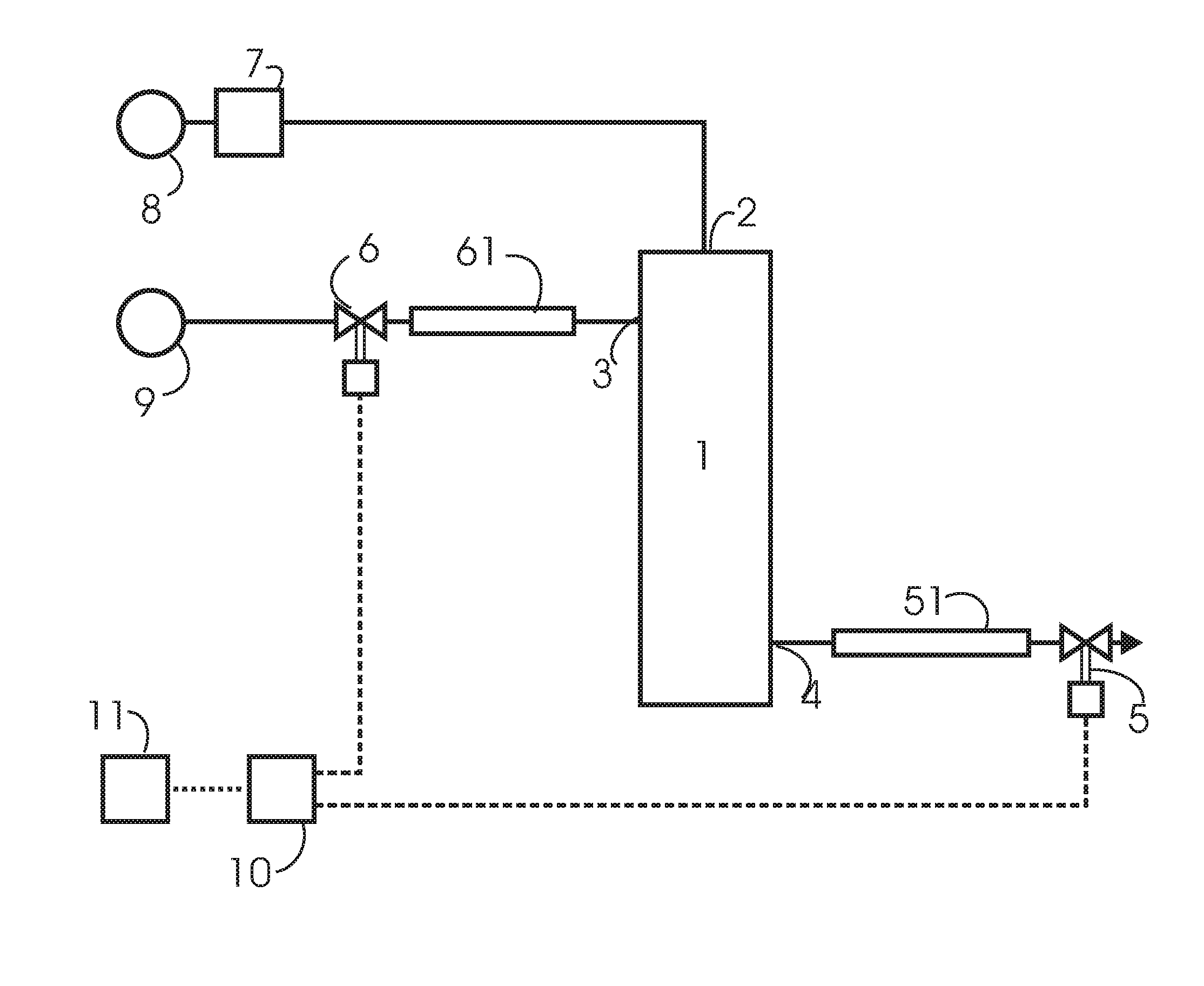
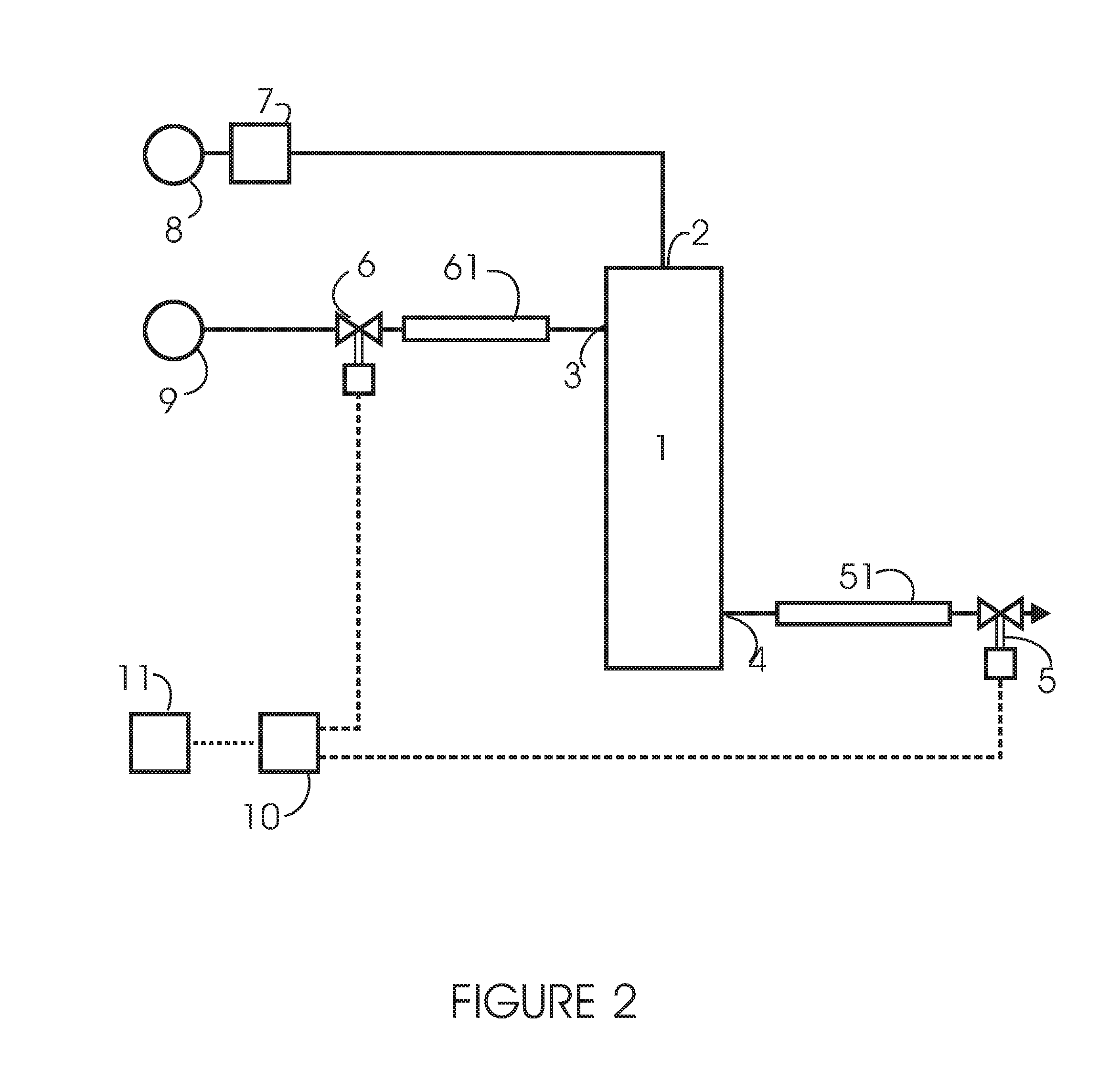
[0087]Dispense liquid flow F4 into the contactor is started at time T0 when both valves 5 and 6 are opened simultaneously, and is stopped at time T1 when valve 6 closes.

[0088]The gas pressure applied to the fibres 1 is maintained at P2 at all times. This pressure determines the maximum amount of gas which can be dissolved in the liquid. As will be explained below, the pressures P2 and P4 are equal prior to the start of each dispense. At such time the liquid contained within 1 will therefore usually b...

second embodiment

[0112]The resulting changes of pressures in response to dispense flow and to operation of valves 5 and 6 through switch 52 and control unit 93 are the same as previously described for the second version of the second embodiment, and illustrated in FIG. 5.

third embodiment

[0113]It will be appreciated that the arrangement illustrated in FIG. 4 requires a manual dispense tap 53 modified to accept flow via valve 5 to its outlet, and that this arrangement results in a small volume being over-dispensed or being wasted. The third embodiment is thus to be preferred in circumstances where the dispense tap 53 is not modified, and in circumstances where it would be undesirable to allow wastage of the small amount of liquid released by valve 5 after closure of valve 6.

[0114]Turning now to the embodiments of FIGS. 7 to 10, for clarity and because the details are not relevant to the present disclosure, details of features and components relating to temperature control of the liquid have been omitted from the circuit diagrams.

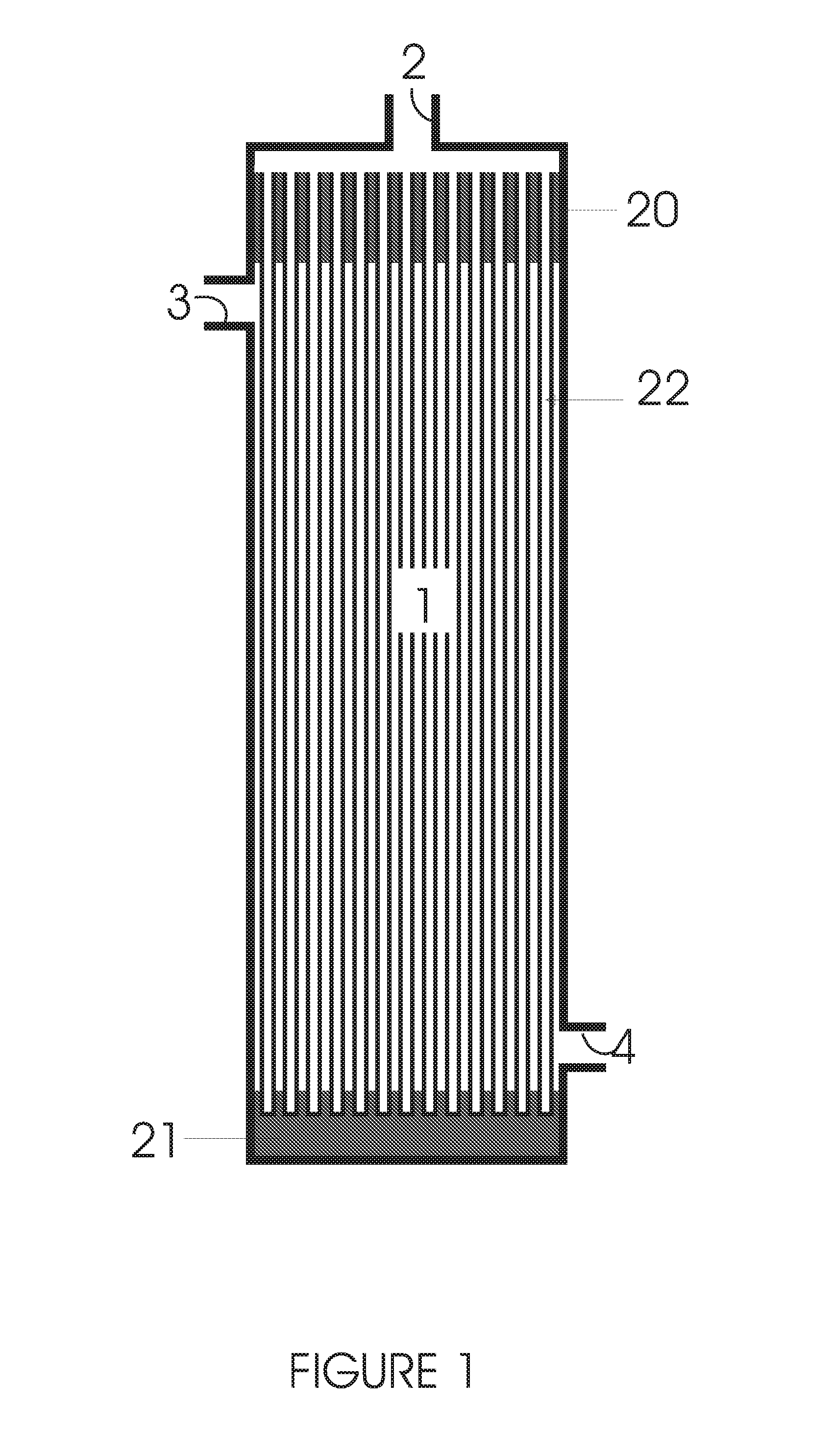
[0115]Gas port 2 of contactor 1 is connected to a gas source 101 via a pressure regulator 102 which is of the type generally known as a relieving regulator, which signifies that it will if necessary vent excess gas from its output side to mai...


PUM

PropertyMeasurementUnit
Timeaaaaaaaaaa
Pressureaaaaaaaaaa
Volumeaaaaaaaaaa

Abstract

A liquid product is dispensed via a membrane contactor. The contactor employs a plurality of gas-permeable hollow fibres. The contactor has a gas port communicating with the interior of the fibres and input and output ports for liquid communicating with space within the contactor surrounding the fibres. A gas comprising carbon dioxide or nitrous oxide is dissolved in the liquid in the contactor. The gas at a controlled pressure is supplied to the gas port. The liquid is supplied at a higher pressure than the gas to the input port for liquid from a supply of such liquid via a first valve having a first valve inlet port communicating with the supply of liquid and a first valve outlet port communicating with the inlet port for liquid. Liquid with the gas dissolved therein is dispensed from the outlet port for liquid via a dispense tap to ambient. The dispensing liquid step includes a start dispense step in which dispensing commences and a stop dispense step in which dispensing is stopped. The first valve is opened with the dispensing tap in the start dispense step, and is closed in the stop dispense step. Pressure build-up is relieved in liquid in communication with the space within the contactor surrounding the fibres after closure of the first valve and while maintaining the first valve closed. The balance between gas pressure and liquid pressure during the systems' standby periods protects the membranes from flooding.

Description

FIELD OF DISCLOSURE[0001]This disclosure relates to the production or dispensing of liquid products. The term “liquid” is used in this disclosure to encompass both true liquids and semi-liquids such as creams, emulsions, and foams that retain at least some ability to flow.BACKGROUND[0002]Some liquids such as draught beverages require certain levels of gases, particularly carbon dioxide, alone or together with other gases, to be dissolved in at least one of the constituent liquids in order to achieve a desired property such as the desired taste and presentation effects in the dispensed drink. Other liquids such as certain dairy products similarly require levels of nitrous oxide, alone or together with other gases to be dissolved in at least one of the constituent liquids in order to achieve a desired foamed constituency upon dispense[0003]The use of gas / liquid contactor modules containing gas-permeable hollow fibres for controlling dissolved gases in liquids is well known. Examples o...

Claims


Application Information

Patent Timeline
IPC IPC(8): B01F3/04B67D1/00A23L2/54
CPCB01F3/04269A23L2/54B01F3/04815B01F2003/04404B67D1/0057B01F2003/04822B01F3/04099B67D1/0072B01F23/23124B01F23/231244B01F23/2363B01F23/2362B01F35/2213B01F35/2209B67D1/0406B01F23/23B01F23/235B01F23/236B01F35/7547B01F23/2364B67D1/0801B67D2001/0827
Inventor PAGE, JOHN KENNETH RURIKPAGE, MARK GEORGE
Owner HEADMASTER
Why Eureka
Try Eureka