Endoscope system and image generation method
a technology of endoscope and image, applied in image enhancement, instruments, catheters, etc., can solve the problem of weak auto-fluorescence used to detect hypertrophy, and achieve the effect of improving the visibility of irregular patterns and reducing the visibility of blood vessel patterns
- Summary
- Abstract
- Description
- Claims
- Application Information
AI Technical Summary
Benefits of technology
Problems solved by technology
Method used
Image
Examples
first embodiment
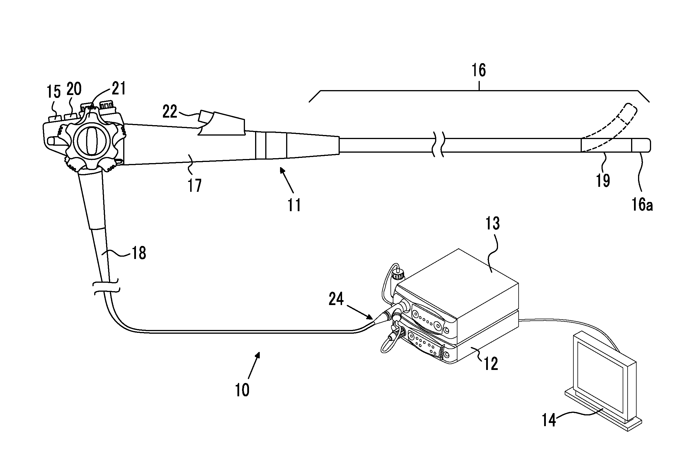
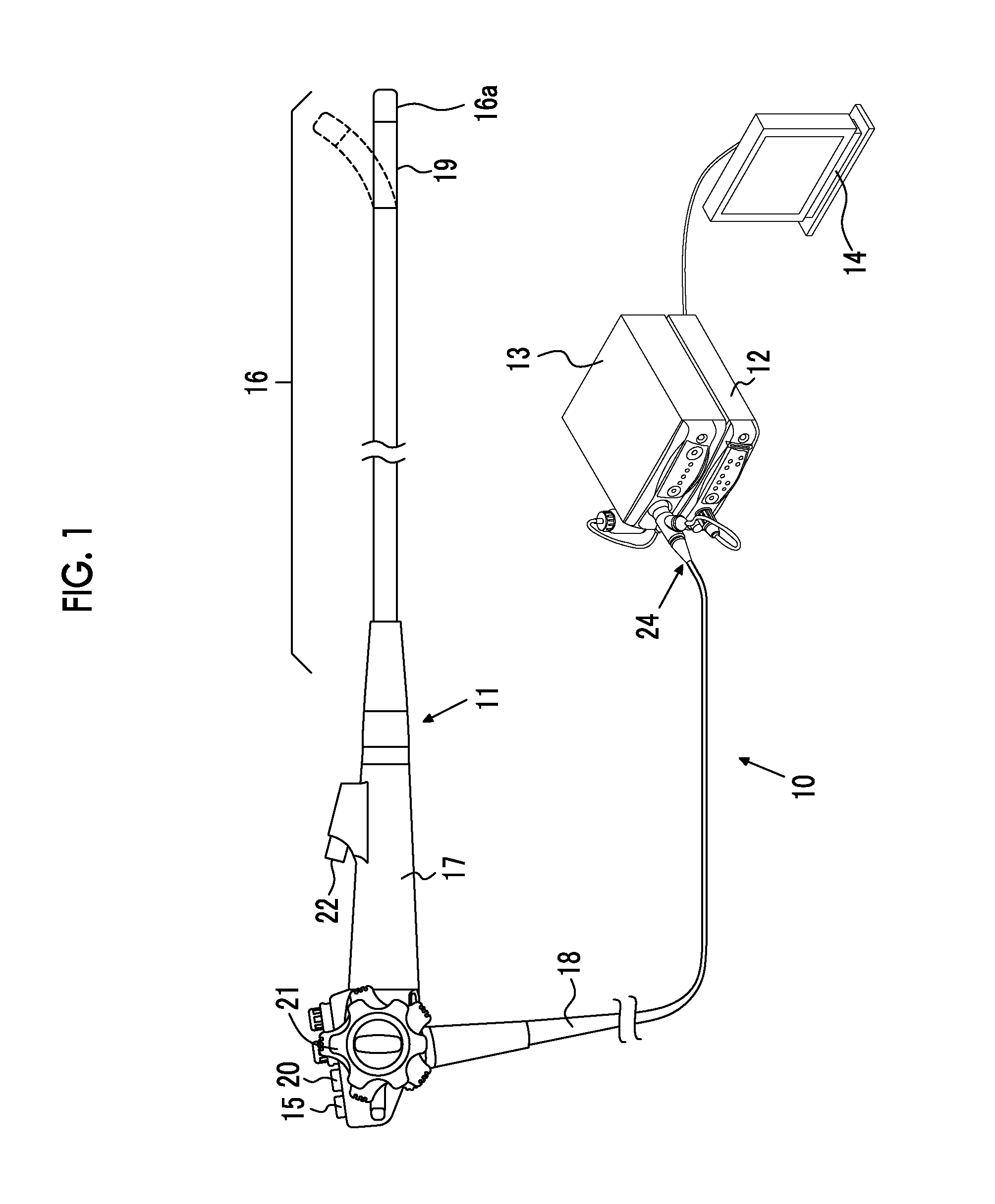
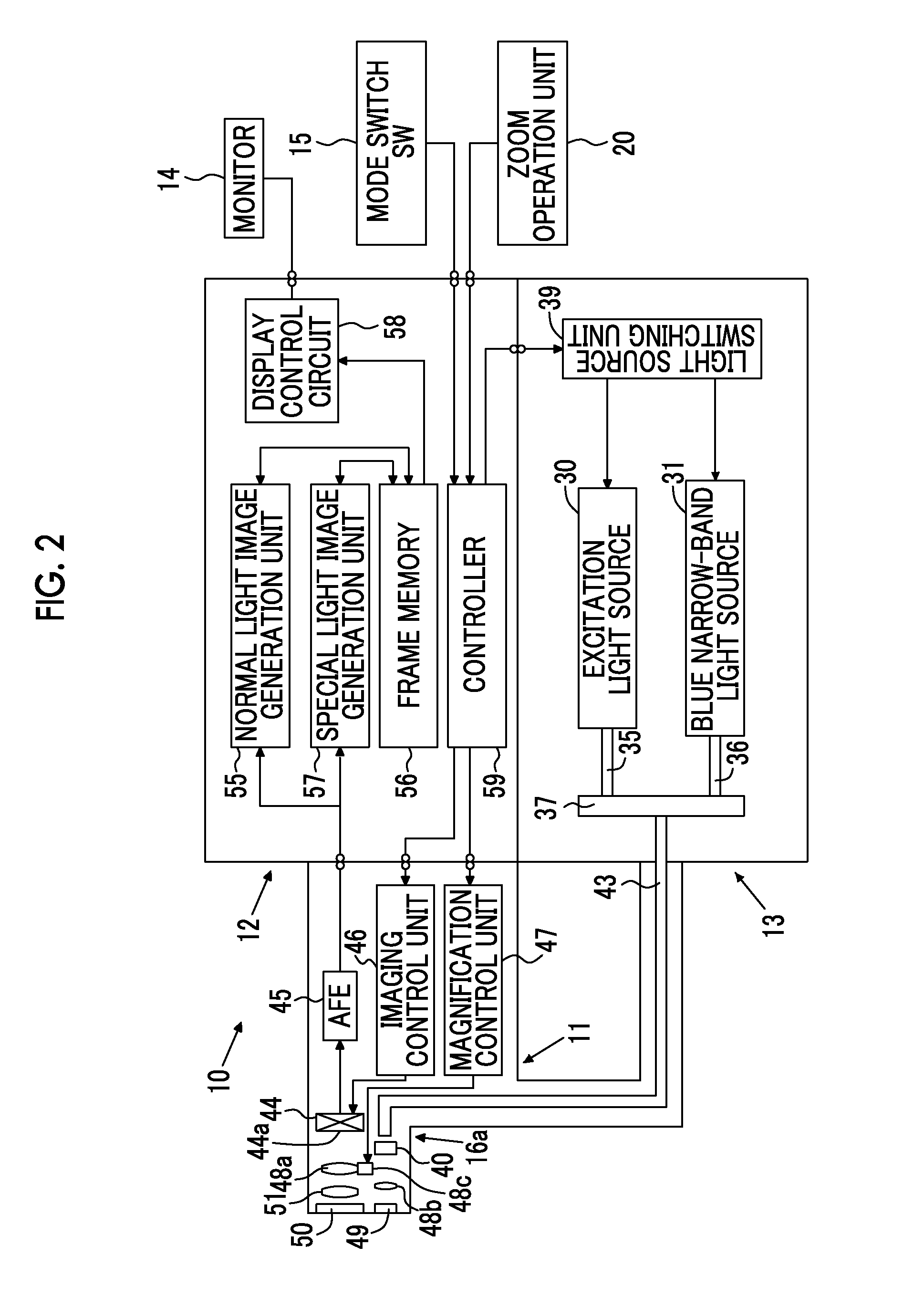
[0044]As shown in FIGS. 1 and 2, an endoscope system 10 of a first embodiment includes: an electronic endoscope 11 (a form of image signal acquisition unit) that images the inside of a subject; a processor device 12 that performs various kinds of image processing on the image captured by the electronic endoscope 11; a light source device 13 that supplies light for illuminating the subject to the electronic endoscope 11; and a monitor 14 that displays an image after various kinds of image processing are performed by the processor device 12.
[0045]The electronic endoscope 11 includes a flexible insertion unit 16 that is inserted into the subject, an operating unit 17 provided at the proximal end of the insertion unit 16, and a universal code 18 that makes a connection between the operating unit 17 and the processor device 12 and the light source device 13. A curved portion 19 obtained by connecting a plurality of curved pieces is formed at the distal end of the insertion unit 16. The c...
second embodiment
[0097]In the second embodiment, when generating a normal light image in the microstructure observation mode and the microstructure and blood vessel observation mode, a correction signal generation section 55a in the normal light image generation unit 55 generates a correction signal B′ by removing the component of the blue narrow-band light BN from the frame sequential imaging signal B+BN, and generates a normal light image using the correction signal B′ and the frame sequential imaging signals G and R. The correction signal generation section 55a generates the correction signal B′ by multiplying the frame sequential imaging signal B+BN by a correction coefficient k that is determined in advance from the relationship between the amount of light of B color and the amount of blue narrow-band light BN or the like.
[0098]In the first and second embodiments described above, a superficial microstructure enhancement image is generated by combining the normal light image with the superficial...
PUM
 Abstract
Description
Claims
Application Information
 - R&D
- Intellectual Property
- Life Sciences
- Materials
- Tech Scout
- Unparalleled Data Quality
- Higher Quality Content
- 60% Fewer Hallucinations
Browse by: Latest US Patents, China's latest patents, Technical Efficacy Thesaurus, Application Domain, Technology Topic, Popular Technical Reports.
© 2025 PatSnap. All rights reserved.Legal|Privacy policy|Modern Slavery Act Transparency Statement|Sitemap|About US| Contact US: help@patsnap.com


