Methods and apparatus for controlling optical properties of light

Inactive Publication Date: 2014-08-07
INVUITY
View PDF13 Cites 49 Cited by
  • Summary
  • Abstract
  • Description
  • Claims
  • Application Information

AI Technical Summary

Benefits of technology

[0019]In still another aspect of the present invention, a flexible illuminated surgical instrument may comprise an optional malleable backing element having a proximal portion and a distal portion, a fiber optic bundle and a non-fiber optical waveguide. The backing element may be manipulated into a plurality of shapes, and the fiber optic bundle has a proximal region and a distal region. The fiber optic bundle is cylindrically shaped in the proximal region, and the fiber optical bundle is flat and planar in the distal region. The fiber optic bundle may be coupled to the malleable backing. The non-fiber optical waveguide is optically coupled with the fiber optic bundle and also is coupled with the malleable backing. As in ot

Problems solved by technology

Illumination of target areas to allow an operator to more clearly observe the target area can be challenging.
External lighting provided by headlamps or wall mounted lights require constant adjustment and can still cast unwanted shadows in the target area.
Additionally, these methods of illumination may not be capable of illuminating a target area that is deep and disposed far below a surface.
Fiber optics may be coupled to tools to help illuminate the target area, but fiber optic systems can be inefficient at transmitting light, and the resulting light

Method used


Image

  • Methods and apparatus for controlling optical properties of light
  • Methods and apparatus for controlling optical properties of light
  • Methods and apparatus for controlling optical properties of light

Examples


Example

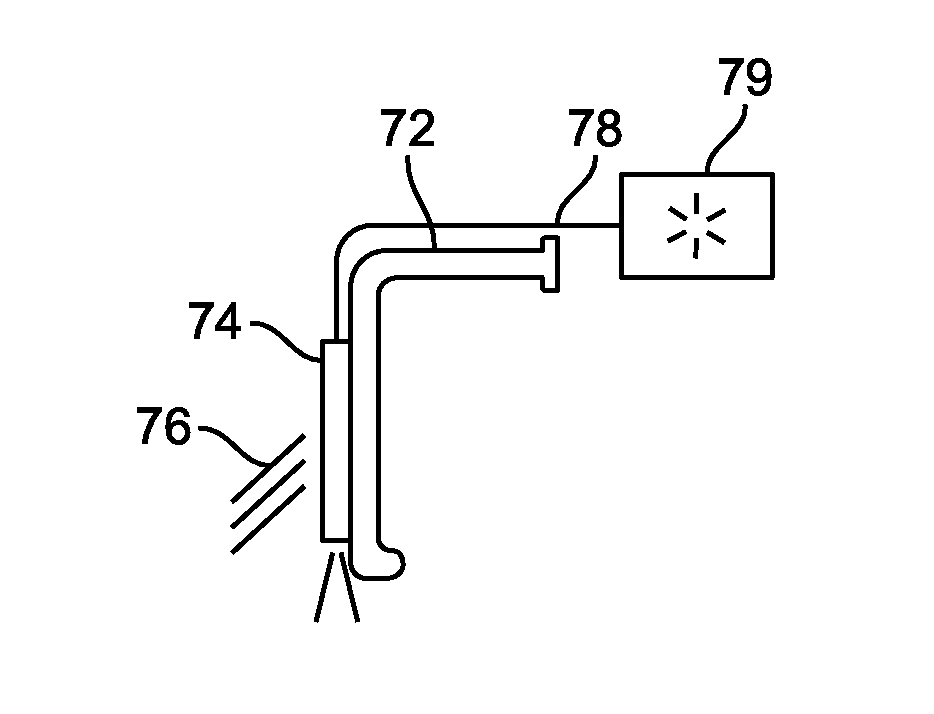
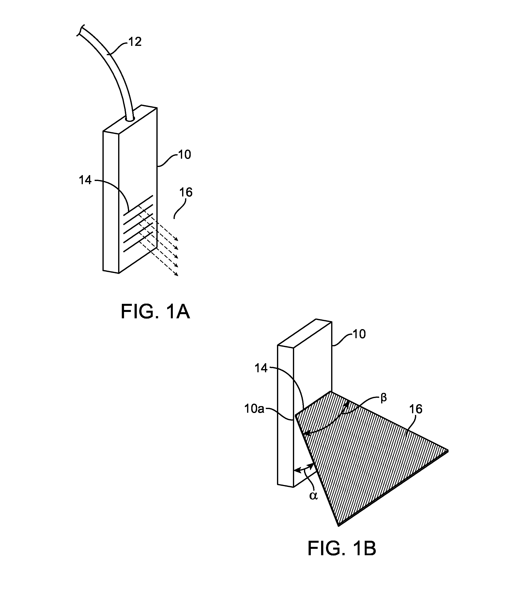
[0060]Many illumination devices and systems provide little control of the light being outputted. For example, fiber optic cables typically only output light radially with a fixed angle from the distal fiber tip. Some optical waveguides deliver light more efficiently and can control light extraction and delivery more effectively such as the embodiment in FIG. 1A which illustrates extraction of light 16 from an optical waveguide 10. Light is input into the optical waveguide 10 typically with a fiber optic input 12 which can be coupled to an external light source. The waveguide includes prismatic surface features 14 on an outer surface of the waveguide. The prismatic surface features 14 extract light 16 from the waveguide 10 and direct the light 16 to a work area such as a surgical field or other target area. Prismatic surface features are described in greater detail in US Patent Publication Nos. 2009 / 0112068; 2009 / 0036744; 2008 / 0002426; 2007 / 0270653; 2007 / 0208226; and 2006 / 0268570; th...


PUM


Abstract

A surgical instrument for illuminating a surgical field has an optical waveguide for transmitting light by total internal reflection. One or more control elements are disposed on the optical waveguide. The control elements extract light from the optical waveguide and control first and second optical properties of the extracted light. Another surgical instrument includes a first and second optical waveguide for transmitting light by total internal reflection. A coupling element is attached to both optical waveguides such that the optical waveguides are movable and pivotable relative to one another.

Description

CROSS-REFERENCE[0001]The present application is a non-provisional of, and claims the benefit of U.S. Provisional Patent Application No. 61 / 705,027 (Attorney Docket No. 40556-726.101) filed Sep. 24, 2012; the entire contents of which are incorporated herein by reference.BACKGROUND OF THE INVENTION[0002]Illumination of target areas to allow an operator to more clearly observe the target area can be challenging. External lighting provided by headlamps or wall mounted lights require constant adjustment and can still cast unwanted shadows in the target area. Additionally, these methods of illumination may not be capable of illuminating a target area that is deep and disposed far below a surface. Fiber optics may be coupled to tools to help illuminate the target area, but fiber optic systems can be inefficient at transmitting light, and the resulting light loss significantly reduces the amount of light delivered to the target area. Attempts to overcome inefficiency of light transmission m...

Claims


Application Information

Patent Timeline
IPC IPC(8): A61B19/00A61B17/02
CPCA61B19/5202A61B2019/5206A61B17/02A61B2017/00946A61B2090/306A61B90/30
Inventor VAYSER, ALEXERISMANN, FERNANDORIMER, DOUGLASTUDURY, GASTON
Owner INVUITY
Why Eureka
Try Eureka